3D Printed Plane Propels Wind Tunnel Testing to New Heights
Aurora created a 1:11th scale wind tunnel model of a Subsonic Fixed Wing transport aircraft using RedEye by Stratasys’ Fused Deposition Modeling (FDM) technology. Image Courtesy of Aurora Flight Sciences.


Latest News
June 1, 2014
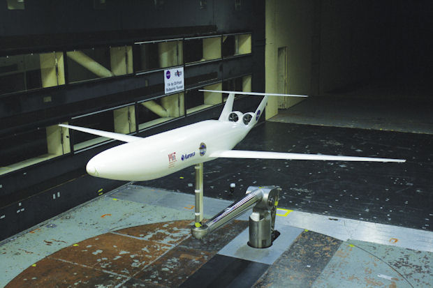
 Aurora created a 1:11th scale wind tunnel model of a Subsonic Fixed Wing transport aircraft using RedEye by Stratasys’ Fused Deposition Modeling (FDM) technology. Image Courtesy of Aurora Flight Sciences.
Fast forward 20 years and try to picture the state of air travel. Thanks to a growing world population and maturing developing economies, air traffic is expected to double in the next 15 years. That will create new levels of congestion and raise concerns about limited runway space, rising fuel costs and a surge in noise and pollution emissions.
As part of an exercise to explore innovations that would address these challenges, NASA embarked on a multi-million dollar Aeronautics Research Mission Directorate concept study to evaluate design approaches for a next-generation aircraft, akin to today’s 737-class fleet, that would go into service in the 2030 to 2035 timeframe. Central to the design study was identifying technologies that would reduce fuel consumption by as much as 70%, significantly cut back on noise and pollution emissions, and enable operation from 3,000 ft. runways that are common to secondary airports outside of major metropolitan areas.
A key phase in the project was a wind tunnel modeling effort that would assess the aerodynamics, propulsion, operation and structure of the proposed concepts. Led by one of the partners on the study, Aurora Flight Science’s Research & Development division, the team took off with Stratasys’ Fused Deposition Modeling (FDM) additive manufacturing technology as a way to shorten its design cycles and maximize limited time slotted in NASA’s wind tunnel facility.
“Typically the turnaround on projects like this is weeks, if not months,” notes Roedolph Opperman, a spacecraft systems engineer at Aurora Flight Sciences. “Because we were working with NASA, we had to schedule time in their wind tunnel months ahead of time and we had to meet our deadlines. With FDM, we were able to get everything done and have an assembled tail in the tunnel in just under a month. That’s unheard of in this industry.”
The “Double Bubble” Design
The concept study for the N+3 subsonic fixed wing transport aircraft—or a jetliner in layman’s terms—called for the project partners to explore three areas of innovation: An aircraft design that could harness liquid natural gas, use a distributed, multiple-engine propulsion system, and would fly about 10% slower than current-day aircraft in order to take advantage of emerging technologies that aren’t supported at current commercial flight speeds.
The team, led by MIT, which included Pratt & Whitney in addition to Aurora Flight Sciences, came up with a radically different design concept for the aircraft, intended to fill the seat of the B737/Airbus A320 class, which accommodates 180 passengers for travel ranging from 500 nautical miles to a transcontinental range trip. Referred to as the D8 series, the concept aircraft took on the shape of a “double bubble” or double-tube and wing, Opperman explains, a design intended to increase lift while allowing for more room to accommodate additional passengers.
The other big change in the design was the placement of the engines—from under the wings where they typically reside, to the back of the plane, riding on top of the aft end of the fuselage. “That was done to take advantage of boundary layer ingestion—a concept that essentially reduces the drag created by the airplane,” Opperman says. “It’s better for the engine.”
Once the primary design concept evolved and was validated with robust simulation testing, it was time to move on to the wind tunnel stage to put the proposed “double bubble” plane model through its paces and prove out the simulation results.
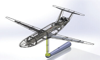 In this full CAD model view of the integrated tail assembly, 3D printed parts were made transparent to show internal metal support structures. Image Courtesy of Aurora Flight Sciences.
Aurora’s role was to develop a scaled-down model of the plane design that would attach to the wind tunnel. The bigger the model, the closer the team could get to resembling the actual aircraft for evaluating drag, the effect on engine placement as well as other capabilities. Initial testing was done at MIT with truncated wings on the 1:11th scale model in order to have it fit in the tunnel. Eventually, the project was moved to NASA’s 14x22-ft. wind tunnel facility to test the full-length wings because the larger tunnel reduces the negative impact of tunnel boundary effects on the measurements, Opperman explains. The team had to schedule the testing period for the NASA facility months in advance and had only a limited amount of time to conduct its wind tunnel verification work, he adds.
RedEye FDM Puts Test Model in Flight
Facing those requirements, and with a heightened interest in 3D printing as the wave of the future for manufacturing, Opperman and his team decided to engage Stratasys’ RedEye rapid prototyping services division to create the test model in an effort to meet its rigorous timelines.
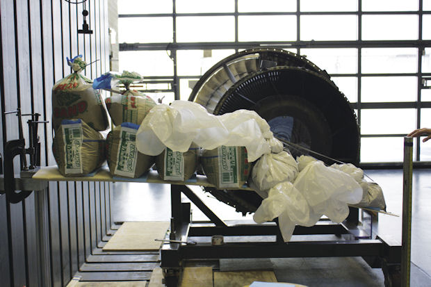 In one test, an FDM wing with an aluminum skeleton was mounted upside down and loaded with 340 pounds to simulate a 300% loading of maximum lift force in the tunnel, resulting in a wing tip deflection of 8 inches. Image Courtesy of Aurora Flight Sciences.
The typical model used in wind tunnel testing is machined out of aluminum, with foam parts used intermittently. It can take as much as a month just to get the machined part—a timeframe that would negatively impact the schedule, he explains. Using the RedEye service, the team submitted designs and received the finished 3D printed versions ready for assembly and finish work in just a few days, which enabled it to meet its aggressive deadlines.
Evaluating possible engine placement and the different variations of the engine nacelle design were also much easier with an additive manufacturing approach, Opperman says. RedEye was able to very quickly print out eight different nacelle shapes during the test period in the wind tunnel, allowing the team to switch out variations and zero in on the optimal shape, he explains. “The clock was ticking—we had six weeks to do all the testing and working with RedEye, we were able to get parts quickly,” he says. “Because everything was changing so rapidly, we wouldn’t have been able to do it if we went the aluminum route.”
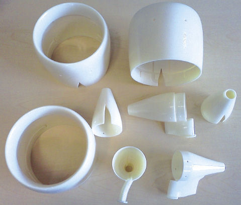 RedEye’s FDM additive manufacturing services were engaged to produce engine nacelle parts for the wind tunnel model. Image Courtesy of Aurora Flight Sciences.
Another benefit of FDM is the flexibility in quickly manufacturing complex surfaces, especially when it comes to the aerodynamically blended shapes of the fuselage, particularly around the integrated engine nacelles of the tail as they are difficult, expensive and time-consuming to machine, Opperman says. The smaller weight also minimizes the support structure required, so it simplifies the design and handling of the model in the wind tunnel.
RedEye by Stratasys could also provide expertise surrounding additive manufacturing practices that Aurora and its team of partners lacked, Opperman says. RedEye is also the single biggest installation of consolidated FDM printers, so it can accommodate large jobs and handle the variety and size of parts and still deliver in a timely fashion, according to Jason Bassi, senior account manager at RedEye.
Because use of 3D printed parts in a wind tunnel was a relatively new application for NASA, due diligence was required in the form of a 400-page report and sample materials to prove that the materials and the process were structurally sound and wouldn’t do damage to the NASA wind tunnel, Opperman says. “NASA wanted to ensure that nothing would break and that there wouldn’t be pieces flying off the model and damaging the tunnel,” he explains. “Because 3D printing is so new [for this application], we needed to show them the calculations and prove that it would be safe.”
Aurora Flight Sciences’ effort to validate the acroylonitrile butadiene styrene (ABS) materials and FDM additive manufacturing process for wind tunnel modeling will go a long way in convincing others of the merits of the approach for this and other serious simulation efforts, according to Bassi.
“The fact that Aurora took the proper steps to certify the materials and the process is crucial,” Bassi says. “The more examples that are tested and validated, the more people have confidence in pushing the limits as to what additive manufacturing can do. Aurora is breaking new ground by validating that the materials work in these scenarios.”
More Info
Subscribe to our FREE magazine, FREE email newsletters or both!
Latest News
About the Author
Beth Stackpole is a contributing editor to Digital Engineering. Send e-mail about this article to [email protected].
Follow DE

