

Latest News
December 14, 2010
By Debbie Sniderman
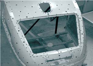 Figure 1. This physical object is covered with targets, ready for photographing. Photogrammetry software extracts geometric information of the reflective targets’ centers. |
The 3D Imaging and Modeling Metrology Group of the National Research Council of Canada and InnovMetric Software, Inc., maker of PolyWorks software, studied 3D measurement hardware technologies and external frame of reference (EFR) monitoring techniques as a basis for research into developing 3D measurement standards. DE looks at some of their findings.
With multiple digitizing technologies available, it is often not obvious which might best serve your needs. This study looked at principles, characteristics and key advantages and disadvantages of both low- and high-density scanning techniques.
Low-density, Single-point Techniques
Single-point measurement tools target and measure one or more specific points at a time by mechanical contact or optical non-contact methods. There are five key reasons that both mechanical contact and optical non-contact, low-density methods are still relevant and important (see Table 1):
1. When combined with mechanical EFR tracking and controlling software, they can produce automated, rapid, repeated 3D surface measurements.
2. They are suitable for measuring parts with highly reflective or transparent surfaces.
3. Difficult-to-reach areas such as deep holes or underbodies may be easier to measure.
4. They can rapidly measure small objects or those with a small number of features.
5. In general, they provide very accurate measurements.
Mechanical measuring methods involve moving a spherical stylus or probe tip to contact an object’s surface and measuring the (x,y,z) position of the tip’s center.
Optical measuring methods project light generated from a lamp, bulb or laser, onto a surface, a reflective marker affixed to a surface, or other reflectors such as spherically mounted retro-reflectors (SMRs). The absolute or relative distance between the scanner and the object is calculated based on the speed of light and the travel time to and from the object (see Figures 1, 2 and 3).
 Figure 2. Simple and coded reflective targets. | 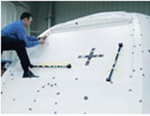 Figure 3. Known-length reference artifacts (the black bars and cross) on a surface. |
 Figure 4. Fixed multi-axis coordinate measuring machine with probe. |
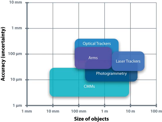
Mechanical tracking for single point measuring techniques retains the same coordinate system as the scanned object. Fixed or portable CMMs’ base or zero does not change as measurements are made (see Figures 4 and 5).
Optical tracking for single-point measuring techniques involves either a laser tracker following the center of a reflective probe, or light-emitting or passive targets affixed to a touch probe mount. Again, these tracking technologies remain in the same coordinate system as the object.
Conceptually, this is similar to a camera pivoting on a tripod mount to take multiple photos of an object, but the tripod is not moved to a different vantage point (see Figure 6).
 Figure 5. An arm-mounted probe obtains coordinate information from multiple points across a surface. |  Figure 6. A laser tracker with a SMR scans multiple reflective targets mounted on a surface. |
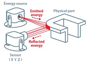 Figure 7. The basic concept of high-density, non-contact digitizing. |
External Frame of Reference
EFR hardware or software monitors the digitizer’s position in real time as it moves around an object, and aligns its many images into a common coordinate system to fully capture and assemble the object’s 3D geometry. EFR is used for precise measurements of large (>1 meter) or complex objects, and can be combined with either low- or high-density digitizing technologies. EFR is required whenever digitizing hardware is moved out of the coordinate system of the object—conceptually equivalent to moving a tripod-mounted camera to another vantage point.
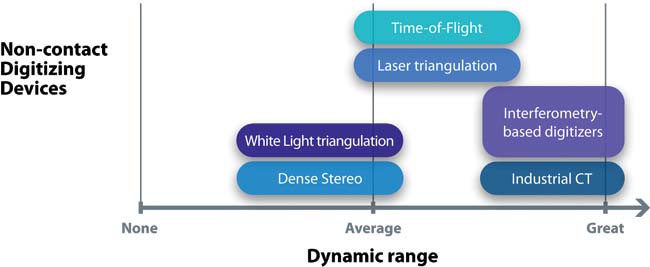
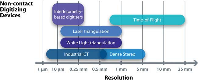
High-density, Non-contact Digitizing
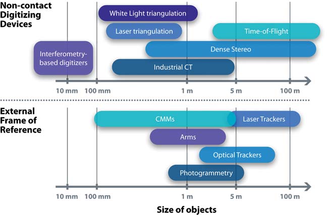
High density, non-contact digitizing methods provide a much faster option for measuring large numbers of points without requiring targets. Since the 1980s, non-contact methods have been preferred for large or freeform surfaces, objects with many features, flexible objects, or fragile objects, because surfaces are not touched by a probe.
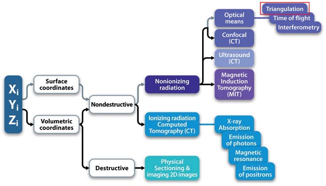 Figure 8. Overview of active, high-density, non-contact digitizing technologies. |
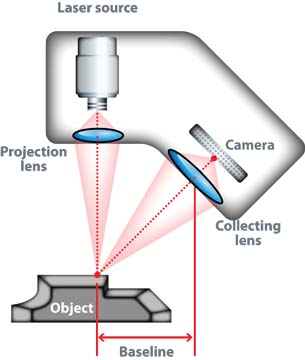 Figure 9. The basic geometric principle of triangulation-based laser digitizing uses a single static laser beam spot. |
Active High-density Scanning
High-density digitizing can be active or passive, but active scanning is the more commonly used method. Conceptually, energy is projected onto a physical part, reflected, and viewed or sensed by an electronic detection device (typically a camera or sensor). Analyzing the position of the reflected energy’s image determines (x,y,z) coordinates of the object (see Figure 7).
Surface 3D digitizers capture an object’s external visible surfaces. Volumetric 3D digitizers capture both exterior visible surfaces and hidden interior geometries.
Destructive Volumetric 3D techniques slowly grind away a small layer of material, digitize what is seen, and repeat until the entire part has been fully digitized and destroyed. Destructive methods are typically used for smaller, low cost, mass-produced parts for which internal structure is crucial, and are rarely used.
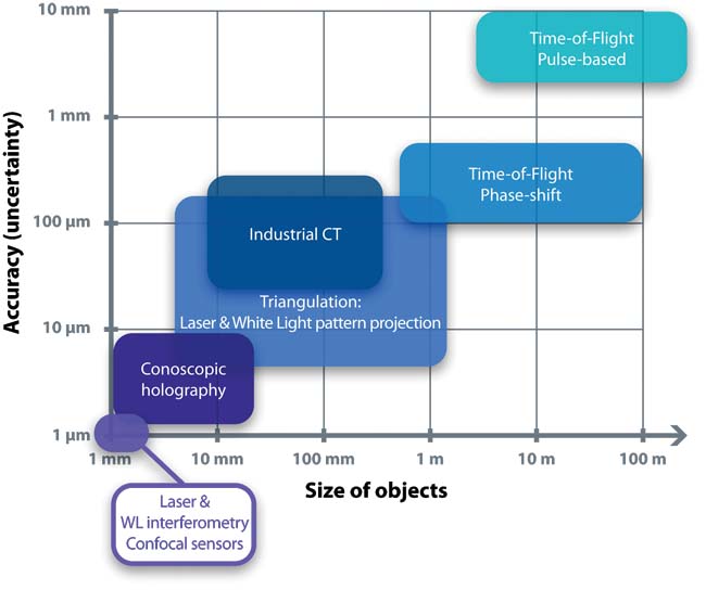
Most digitizers used in industrial applications use non-destructive techniques. About 90% of close-range, high-density digitizers belong in the triangulation category enclosed in red (see Figure 8).
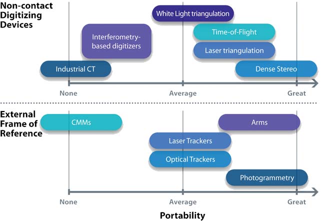
Table 2 summarizes principles and characteristics of high-density measuring technologies and associated EFR methods.
Table 1: Low-density/Single-point Measurement Technologies |
Name of Method | Contact/Non-contact Method | Incremental or Absolute Distance Measurement (ADM) | Detection Method | What is Measured or Algorithmically Extracted | Type of Tracking Along Surface | Portability |
| Traditional Fixed CMM | Contact | Absolute | Center of Spherical Tip Contacts Surface | Probe tip’s center (x,y,z) position is recorded, true surface calculated based on a compensation vector, displacement in time | Fixed multi-axis coordinate measurement machine (CMM) | Immobile technique requiring part be brought to the measurement tool |
| Portable CMM: Articulated Arm | Contact | Absolute | Center of Spherical Tip Contacts Surface | Probe tip’s center position is recorded, true surface calculated based on a compensation vector, displacement in time | Six-axis or a seven-axis articulated (jointed) arm | Arm with many flexible joints, brought near the part to be measured |
| Portable CMM: Laser Tracker | Contact | Either or both, Interferometer based or ADM | Center of a spherically mounted retro reflector (SMR) contacts surface | Laser beam is locked on center of SMR; azimuth and elevation angles of laser beam are measured, distance between laser tracker origin and SMR is measured | Laser beam tracks the 3D coordinates of SMR’s center | Portable; tracker is brought near the part to measure |
| Portable CMM: Optical Tracker | Contact | Absolute | Center of a spherical tip mounted with light-emitting or passive targets contacts surface | Center of all visible light-emitting or passive targets affixed on contact probe | Tracks reflective or emitting targets | Portable; tracker is brought near the part to measure |
| Photogrammetry | Non-contact (but targets do contact object) | Absolute | Optical: Digital camera photographs targets on a surface | Center of light-emitting or passive targets affixed or mounted on object’s surface | Tracks targets whose position are determined by photogrammetry | Portable; cameras are brought to the part to be photographed |
Table 2: High-density Non-contact Measurement Technologies
|
Triangulation-based Laser Techniques
Laser triangulation digitizers project a line or a single spot (projected as a line using mirrors) onto an object, which reflects and is imaged by a camera. Knowing projection and collection angles relative to a baseline determines a triangle’s dimensions and the coordinates of a point on the surface (see Figures 9, 10 and 11).
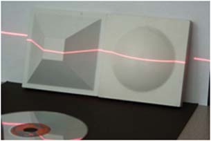 Figure 10. Another form of triangulation-based laser digitizing, with a laser line projected on digitized object. |  Figure 11. A handheld laser scanner sweeps across a surface. Figure 11. A handheld laser scanner sweeps across a surface. |
These close-range laser techniques offer excellent depth resolution on large parts, and can measure small detail such as borders, edges and cracks. They are more robust to ambient light sources, and less subject to noise from object color or luster.
There is a performance trade-off, however, for technologies with a baseline, such as triangulation. Larger baselines are more accurate, whereas smaller baselines exhibit fewer occlusion effects. The laser speckle effect (see Figure 12) also limits this technique’s accuracy on optically rough surfaces.
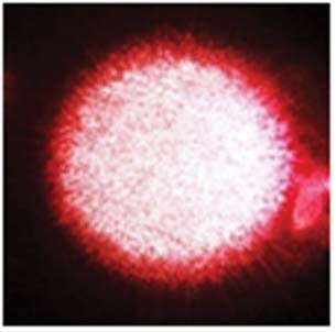 Figure 12. An example of the laser speckle effect. | 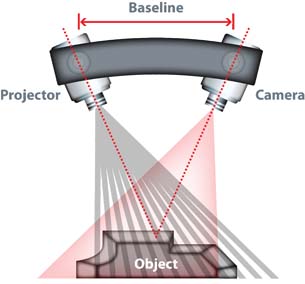 Figure 13. The basic geometric principle of fringe-based projection digitizing. |
Fringe-based Projection Techniques
Successive images of fringe patterns are projected onto an object, and one or two high-density cameras capture surface images. Enough fringe patterns are projected until a grid of object coordinates can be formed from intersecting reflections on individual camera pixels (see Figures 13 and 14).
 Figure 14. This fringe-based white light projection digitizer is combined with optical tracking EFR. |
Detailed measurements can be made by taking a series of photos with different stripe pattern widths (phase-shifting), as shown in Figure 15. This technique is known as white light time-multiplexed pattern projection.
These close-range measurement techniques offer good accuracy and lateral resolution along two axes, and are fast to measure objects with low-curvature surfaces. Important limitations of fringe techniques, however, are that they lack the dynamic range needed to scan shiny finishes, are slow to measure objects with intricate details, and suffer from occlusion effects, requiring additional shots depending on the size of the object.
 Figure 15. Object to digitize with interference fringe patterns for coarse and fine depth measurement. |
| Before You Buy Benchmarking involves evaluating sample scans and comparing results to known nominal values. It can highlight unpredictable or non-obvious issues, and can help the user gain confidence in a technique and its results. It can also help determine whether additional external reference hardware or software is needed for your specific application.Marc Soucy, president of InnovMetric, stresses that benchmarking allows a wide variety of software options, plug-ins and add-ons to be demonstrated, that can control digitizing hardware or reduce sample or evaluation time. He suggests that benchmarking should include repeated measurements of a known part before making a system purchase, and recommends benchmarking the digitizing and EFR technologies under consideration together. |
Industrial Computer Tomography (CT) Techniques
These close-range, turnkey techniques produce a complete volumetric point cloud of an object, and in some cases, allow porosity and internal defects to be seen. They are very accurate techniques. Unfortunately, CT can be quite expensive, and calibrating and measuring parts made with different materials is a challenge.
Time-of-flight (TOF)-based Laser Techniques
Pulse-based and phase-shift TOF techniques are co-axial technologies with no baseline and therefore no occlusion effects. They are compatible with conventional surveying tools such as GPS, GIS and LIDAR. Their acquisition speeds are suitable for measuring objects such as cars, planes, trains or buildings. One disadvantage of TOF laser techniques, however, is that they are less accurate than close-range techniques.
Passive High-density Scanning
Also known as dense stereo vision (DSV) digitizing, passive scanners capture high-resolution photographs of surfaces lit with high-lumen external or ambient light, instead of radiating light. DSV techniques use multiple cameras and processing software, and are useful for mid-range scanning. They are simple to set up, have rapid measurement times, and some commercial versions provide automated surface matching. Drawbacks include being less accurate than close-range techniques due to occlusion effects, and only working on parts with texture
|

3D Scanning Terms | ||||||||||||||||||||||||||||||||||||||||
|
More Info:
National Research Council Canada
Debbie Sniderman is CEO of VI Ventures LLC, an engineering, manufacturing and R&D consultancy. Contact her at VIVLLC.com.
Subscribe to our FREE magazine, FREE email newsletters or both!
Latest News
About the Author
DE’s editors contribute news and new product announcements to Digital Engineering.
Press releases may be sent to them via [email protected].


