3D Scanning Heads Toward Seamless CAD Integration

As the 3D scanning industry matures, inspecting and creating designs becomes easier.

As the 3D scanning industry matures, inspecting and creating designs becomes easier.

By Debbie Sniderman

Not so long ago, 3D scanning hardware systems contained proprietary hardware and software packages that made it difficult and time-consuming to integrate the scanned points with CAD software. But over the last five years, as the 3D scanning industry has matured, producers have responded to user needs “and are partnering together to improve integration with CAD packages.

DE spoke with a metrology service provider, a 3D scanning hardware vendor and a bridge software producer to find out more about the concept of seamless integration.

Better Bridge Software

The majority of Exact Metrology’s service business is scanning parts and creating CAD models for overloaded customers. Some send 3D scan data from X-ray or computed tomography (CT) scanners, requesting CAD files. The company uses many different scanning and 3D technologies for creating models of small-scale parts “up to buildings or city blocks.
Exact Metrology
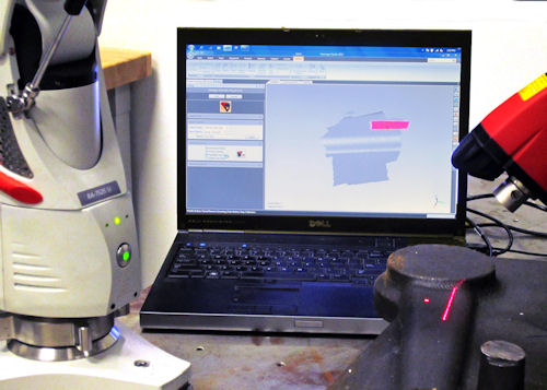
Exact Metrology scans a casting with a Hexagon Absolute SI arm/scanner directly into Geomagic software.
“While scanner manufacturers have their own proprietary software to control the scanner and collect data, more are getting out of the software business,” says Greg Groth,  Exact Metrology’s Milwaukee service manager. Groth adds that hardware manufacturers are allowing third-party software packages to develop plug-ins to integrate with scanners and control data gathering: “They’re taking the attitude of ‘we’ll handle the hardware and let someone else handle the software.’”He describes this third-party software as “bridge software,” a connection platform to get from Point A (scan data) to Point C (a CAD model). This bridging software is sometimes called digital shape sampling and processing (DSSP) software, point cloud software, or generically, middleware. According to Groth, “It eliminates the need to rely on the software supplied by the hardware manufacturers. It’s plug-and-play.” Bridge software can accept data from any 3D scanning capability, whether a few hundred points from a coordinate measuring machine (CMM) or multi-gigabyte data sets from long-range scans. It acts as a filter.
SolidWorks
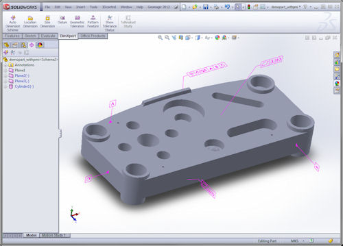
A SolidWorks CAD model ready for export with model-based datums (MBD), product manufacturing information (PMI) or Geometric Dimensions and Tolerances (GD&T) callouts defined.
“We haven’t found a successful CAD package that can open heavy data sets, so bridging software takes them and uses logical, formula-based filtering to remove unnecessary data, keeping enough data that is still workable,” Groth explains. The software removes redundancies and overlaps in scan data. It also allows you to change the sensitivity or spacing of the points before bringing it into CAD. Instead of importing millions of points that describe a flat surface, you can filter down a lot of that data.Bridge software also allows you to manipulate the scanned data, removing imperfections or cracks if they aren’t desired as part of the CAD model.“You can remove these in CAD, but not with the accuracy,” Groth points out. “Any time you go from 3D data to a parametric CAD surface, you lose some accuracy. This ability is good because in CAD, processing can be data-intense. If your part is 0.75363 in. in the real world and the design is 0.75 in., the software allows you to whittle away the imperfections or correct dimensions that may be off.” Groth says that without bridge software packages, there is no efficient way to get scan data into CAD. They are a necessity because CAD packages can’t handle huge data sets.“It has a CAD-like structure and builds parametric features on top of the 3D data sets,” he says. “It converts the millions of points and triangles into a format that can be brought into most CAD platforms. It also provides good rendering points, giving a visual aid before exporting. Before, you hoped that you got everything. Now,  it’s easy to verify ahead of time.” The process for getting scan data into CAD used to involve three different software packages: scanner software, data processing software and CAD software. Now, it usually only involves two.“I can plug scanning hardware into bridge software and scan natively inside that program to collect data. It is becoming much faster,” Groth says. “Years ago, it could take a week to scan something the size of an automobile, read the data into older bridge software that had limited tools, and create a CAD file. Now, a scanning tech and software tech can scan the same part in a couple hours, and have a workable CAD file by the end of the day. The time savings from better bridge software are huge.” While bridge software transfers data to CAD faster, and the data making it into CAD is getting more accurate, Groth says he believes much more could be done on the CAD side.“Hopefully the CAD packages will follow suit and begin to accept 3D scan data better,” he says. “Unfortunately,  we don’t see many CAD manufacturers looking into plug-ins for scanning efficiently. 3D scanning has been around for more than 15 years. It’s amazing that a minimal amount has changed on the CAD side as far as accepting huge data sets.”

Open Hardware for Scan-To-Design Applications

Alex Lucas, business development manager of Nikon Metrology’s Scanning Products, agrees that it is becoming easier to gather and process point cloud data for copying a part,  building a descriptive database to archive, or for finite element analysis (FEA) customers who want to develop a CAD model. For workflows that start with a “clean slate,” or no model already developed in CAD, Nikon Metrology’s application programming interfaces (APIs) allow scanning hardware to accurately and reliably interface with software that can control and fully manage point cloud acquisition. They also allow parameter modification and qualification or calibration routines.
Nikon Metrology
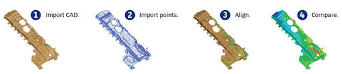
The inspection workflow using Nikon Metrology’s Proprietary Focus Software involves scanning a part, importing its CAD data and the scanned points, and aligning and comparing the two datasets.
“We used to develop our own software, but it makes more sense to align and partner with those who have spent the time and effort developing this software for the industry,”  Lucas says. “We’ve partnered with half-a-dozen third-party software providers who can take point cloud data and generate a CAD model. All of our laser scanners now integrate with third-party software.” As laser scanning has become more popular, he says, there are fewer hardware providers and more software providers. “Five to eight years ago, we wouldn’t find any point cloud software packages offering direct links to CAD that were able to output a native file format,” he adds. “Now, quite a few software developers offer that ability, so designers can very quickly export their data and apply even greater tools.”

Retaining Control During Inspections

On the inspection side, Lucas says, the integration story is different. Inspection workflows involve scanning a manufactured shape and comparing that to an as-designed shape. This process also involves one or two software packages in addition to CAD. For the scanning step, Lucas says Nikon Metrology prefers that customers use Nikon’s own proprietary software, such as the stand-alone FOCUS API, for handheld inspections.“Part of the point cloud inspection process is dictated by the features and surfaces that a user wants to check,” he explains. “Our specialty is controlling the scanners and the entire inspection process, so we want to control what data goes into it by integrating with the data brought in from CAD directly, rather than allow third-party control of that data.” The next step involves software that accepts user-input scan data, stitches together a 3D model, and compares it against a definition. This could be accomplished with a manufacturer’s standalone package or third-party bridge software. Most of the time, 3D geometry or shape data provided into that software comes from a CAD model “but it’s not the complete file, and it contains limited “dumb” geometry information without feature, history or product manufacturing information (PMI).“Even though our software for inspection scanning is proprietary, our hardware provides industry-standard formats for transferring data,” Lucas says, offering discrete ASCII x, y and z data in column or .csv format, and polygonal mesh .stl files as examples. “We also output in several proprietary file formats, which may lock a user into a certain software company’s file extension.”

‘Perfect Integration’

Geomagic is an example of bridge software that is used for both types of scanning applications mentioned above. Kevin Scofield, Geomagic’s senior product manager for metrology and modeling applications, says he sees requests to include more information from CAD models during inspections, such as dimensions, freeform geometry-like features, or other metadata that accompanies the geometry.
Geomagic
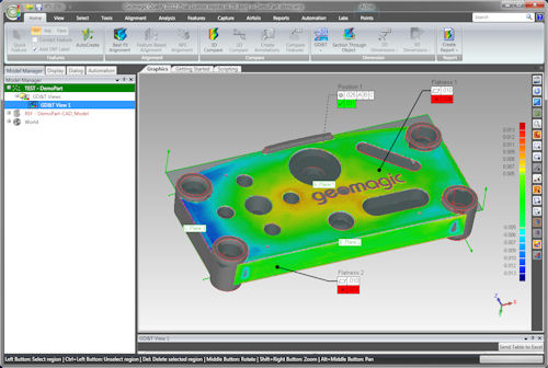
The GD&T callouts from the CAD model are automatically analyzed and reported after being imported.
“In the future,  better integration between CAD and portable metrology software, our specialty area, happens with model-based definitions, or MBD,” he says. “The world is getting away from defining a model with 2D drawings and paper, and is including everything inside “the geometry, the material, and even information about how it’s built. “Geomagic and our competitors are pushing in the direction of absorbing and using that data now,”  Scofield continues. “Our charter is to keep up with that pace, and push toward perfect integration. Ideally, a part that is fully defined in CAD will be imported into Geomagic. A user can scan and inspect without having to set up any dimensional parameters. They should be able to read more data from CAD. There’s no reason to think that we can’t reach this dream scenario. We’re striving toward that now.” Scofield maintains that extra data from PMI and MBD will make the inspection process move faster,  because users won’t have to redo the work.“Importing expected dimensions when you import the model will save time by getting rid of the need for typing or entering redundant dimensions on a screen, when the designer has already stored that information with the model,” he adds.

Improving Relationships

On the hardware side,  Scofield says Geomagic has strategic relationships with more than a dozen major manufacturers of digitizers and scanners that have unlocked their hardware and released APIs to use their software. “Manufacturers often release new hardware devices and versions, so we’re constantly keeping up with their latest developments,” he says. On the CAD side,  Geomagic licenses third-party CAD importing libraries that allow it to read in and offer native CAD file formats. It builds these libraries into its software. Scofield says Geomagic used to charge as much as $2,500 per CAD importer, but the company has since recognized the value it is adding and now provides them for free.“There is a lot of upkeep on this end, too, as CAD companies revise their software versions. We’re always getting and testing new libraries. Between the hardware companies and the CAD companies, there’s a lot to keep our eye on,” he says. Scofield points out that it’s rarely asked why CAD programs don’t interact directly with hardware,  or why software like Geomagic can’t work inside of CAD. But he knows the answer. “Because rendering time and memory requirements are extremely high for millions of discrete points, no one cares to do it. There’s more stress handling large files and memory. It doesn’t mean that it’s not the right thing to do, but it’s a reason the big CAD companies haven’t done it.“But that is another possibility for the future,” he says. DE

Debbie Sniderman is an engineer, writer and consultant in manufacturing and R&D. Contact her at VIVLLC.com.

More Info

Exact Metrology Geomagic Nikon Metrology Nikon Metrology Point Cloud Software API

Share This Article

Subscribe to our FREE magazine, FREE email newsletters or both!

Join over 90,000 engineering professionals who get fresh engineering news as soon as it is published.


About the Author

DE Editors's avatar
DE Editors

DE’s editors contribute news and new product announcements to Digital Engineering.
Press releases may be sent to them via [email protected].

Follow DE
#2809