


October 7, 2016
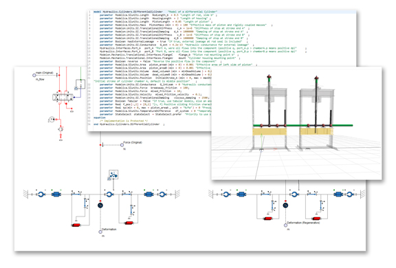 A model of a hydraulic press in MapleSim, with an extract of the underlying Modelica code. (Image courtesy of Maplesoft)
System models, recorded in popular languages like Modelica, and simulation models, authored in FEA software like ANSYS, STAR-CCM+, and Abaqus, traditionally live in separately worlds, managed by different domain experts. But perhaps it’s time for the the two to come together.
Laurent Bernardin, chief scientist and executive VP of Maplesoft, said, “In the past, it was fine to keep the detailed designs at the component level, and, later in the process, fit these parts together. That was a process well-understood. But now it’s no longer enough to just work on your own part. Regulatory environments are becoming much more stringent. Products are getting much more complex. You have to consider your part’s role in the entire system. Manufacturers are now building virtual prototypes as early as possible, to show the behavior of the entire system.”
The collision of the disciplines has spawned some partnerships among software vendors catering to different domains. One is between Maplesoft, responsible for the Modelica-based system-modeling software MapleSim, and Altair, known for its optimization and simulation solvers. The handshake, announced in June, will let Altair “access OEM Modelica, the object-oriented modeling language engine of MapleSim ... Altair will embed and leverage the MapleSim Modelica Engine to support their model-based system development strategy and focus on multi-physics simulation.”
Bernardin described MapleSim Modelica Engine as “a compiler and a series of solvers for Modelica projects.” He explained, “Modelica is open source so you can use it to view system documents, but MapleSim can transform your Modelica projects into executables. It also comes with solvers so you can use it to run system simulation”
FEA and CFD solvers could help you optimize the topology or shape of your product at the part and component level. By contrast, system modeling helps you fine-tune the entire product’s performance by balancing how the different parts interact with one another.
“You might have a battery in your system model, which also connects to the power train and the chassis,” Bernardin pointed out. “The same battery is part of your FEA or CFD model. Even if the models [in your system-level view and component-level views] contain different levels of details, you have to make sure they’re consistent and the data can flow from one to the other.”
The ultimate goal for manufacturing is to work with a single model that can account for CFD, FEA, electrical, thermal, and other types. Bernardin said, “That is a bit too far in the future. Today, different groups still work on their parts using their own tools. But the system model now serves like a glue to keep them together.
Subscribe to our FREE magazine, FREE email newsletters or both!
About the Author
Kenneth Wong is Digital Engineering’s resident blogger and senior editor. Email him at [email protected] or share your thoughts on this article at digitaleng.news/facebook.
Follow DE

