A Design-Validation-Production Workflow for Aerospace Additive Manufacturing


Latest News
November 10, 2016
 Dear DE Reader:
Uncertainty, thy mother is assumption. Today’s Check it Out link takes you to an in-depth technical white paper that describes a design, analysis and physical testing workflow that can help you cull out uncertainties in simulation models, optimize designs and raise your confidence in your models.
The title “A Design-Validation-Production Workflow for Aerospace Additive Manufacturing” may lull you into assuming this paper is solely for aerospace people. Yet if you design, analyze and test part robustness in any industry, you can map this paper to your requirements easily.The thesis is that 3D printing is used for one-offs, small-lot parts and for parts difficult to make with traditional manufacturing processes. The digital-to-physical link that 3D printing offers means you can design your model and 3D print a part that meets stringent requirements.
Traditional workflows, however, rely on simulations that use the uncertainties inherent in your design assumptions. Prototyping tests those assumptions late in the cycle, which tends to jack up costs and time with rework. The solution the paper offers is to measure simulation accuracy during the mid-stages of your design cycle using a process called CAETestbench. It seems an interesting and elegant solution.
Every element of the engineer workflow and toolkit appears to play a role in this paper: CAD, material databases, FEA (finite element analysis), topology optimization, inter-application connectivity, documentation and generating revised solid geometry from optimization concept results. A key is leveraging 3D printing then validating simulation accuracy mid-way through development rather than prototyping near the end of the process.
What this means is that CAETestbench has you 3D-print parts with the exact materials and process you assume the final part will use. You subject that part to the strains and stresses it must handle until deformation. You then use a component called Digital Image Correlation with a solver like Altair’s OptiStruct to compare the deformed physical part with your simulation-predicted failure to validate your solver’s ability to model the 3D part correctly.
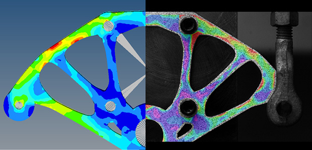 This Digital Image Correlation (DIC) image shows a comparison of measured strains and the predicted strains from an OptiStruct FEA (finite element analysis) model. Image courtesy of Altair Engineering Inc.
The paper steps you through the CAETestbench process from material modeling, simulation, 3D printing, validation and optimization. Well-known engineering tools come and go as the project progresses. Rich technical details, images and tables broaden the discussion every step of the way.
“A Design-Validation-Production Workflow for Aerospace Additive Manufacturing” is a winner. Hit today’s Check it Out link, download your copy and then compare it to your workflow. Well worth it.
Thanks, Pal. – Lockwood
Anthony J. Lockwood
Editor at Large, DE
Subscribe to our FREE magazine, FREE email newsletters or both!
Latest News
About the Author
Anthony J. Lockwood is Digital Engineering’s founding editor. He is now retired. Contact him via [email protected].
Follow DE

