Finite element model of A350-1000 XWB left wing excluding control surfaces. Image courtesy of Airbus.

Latest News
November 1, 2016
Airframes are designed to deflect in response to aerodynamic and gravitational loads during flight. These deflections in turn load the mechanisms riding on the airframe that move the primary flight control surfaces to maneuver the aircraft. The airframe manufacturer must ensure that deflections of these mechanisms at any point in the flight envelope do not affect their operation.
 Hinge 7 is located on the horizontal tail plane of the A400M. Image courtesy of Airbus.
For example, the Airbus A400M elevator is connected to the horizontal tail plane (HTP) with eight hinges that form a straight line when the wing is undeformed. Seven of these hinges are floating hinges, which can float in the hinge line direction. When the HTP structure is loaded, it deforms, deforming the hinge line. The multi body simulation (MBS) model shows the location of hinge 7, which is used to move the elevator and the drawing below the model shows a cross-section of the hinge. The gap g2 in the drawing allows the red lug to slide on the green pin.
 Hinge 7 mechanism detail. Image courtesy of Airbus.
Challenge
The European Aviation Safety Agency (EASA) regulation CS-25 section 683(b) requires that airframe manufacturers certify that the primary flight control surfaces used to maneuver the aircraft remain free from jamming, excessive friction, disconnection and any form of damage due to deflections of the aircraft structure. In the past, Airbus validated this requirement by building test rigs for each new aircraft to deflect the structural assemblies based on forces acting on the airframe.
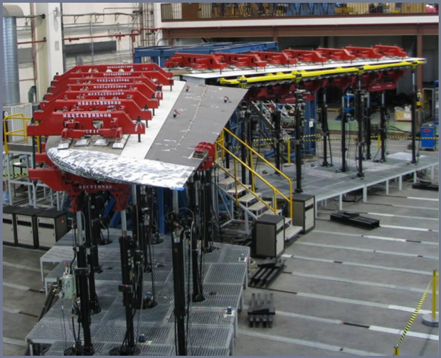 Rig used to test hinges on horizontal tail plane. Image courtesy of Airbus.
The largest of the test rigs was large enough to enclose the wing of a wide body aircraft and was extremely complex because of the need to apply forces to the structure at many different locations in order to approximate the forces experienced during flight. The test rigs cost millions of dollars and took months to build and considerable additional time and money was required to perform the testing. One of the limitations of this approach was that testing could not begin until detailed design had been completed and a prototype of the aircraft was built. Problems identified by testing were often quite expensive to correct at this late stage in the design process. Another limitation was that the time involved in physical testing put strict limits on the number of different load cases and configurations that could be tested.
Solution/Validation
Airbus management decided to try to change the means of compliance with this regulation from physical testing to simulation. Adams multibody simulation (MBS) software was selected because of its ability to model complex mechanisms and to incorporate finite element models that are used to predict deformations of the airframe. The Airbus Multi-Body Simulation team decided to simulate the hinge of an A400M horizontal tail plane and predict the gap g2 in hinge 7 under the loads used in physical testing as proof of concept.
An Adams multi-body simulation was created with the same boundary conditions as the real test. MSC Nastran FE models were created of the HTP and left and right elevators. A modal neutral file (MNF) was exported for each flexible body and coupled to the Adams model. The MNF consists of all boundary modes expressed in physical coordinates and a truncated set of elastic modes expressed in modal coordinates. The FE model of the HTP has about 35,000 degrees of freedom (DOF) while the flexible body defined by the MNF has only about 100 DOF, providing dramatic time savings during the solution process.
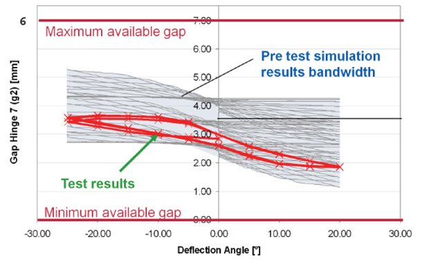 Simulation results shown in grey match up well with test results shown in red. Image courtesy of Airbus/MSC Software.
An in-house Airbus CFD code was used to determine the pressure on the wings during various flight conditions. These loads were converted to forces on the Adams model. The Adams model simulated the deformation of control surfaces under flight conditions and the impact on the hinges. Uncertain parameters such as friction coefficients for the translation of the lug and the pin and the manufacturing variation for several key dimensions were varied between defined limits and combined with the Latin hypercube method, yielding 500 different combinations of parameter values.
The MBS model was solved for these 500 different combinations and resulting gap was evaluated over the deflection angle of the elevator for each run. The pre-test simulation results bandwidth due to parameter variation is shown in the graph in grey. The test results are shown on the graph in red and they fit well within the predicted range. Further validation of this approach was obtained by performance different simulations on the A400M rudder, A380 elevator, A380 ailerons and A350-900 1g wing bending tests.
“Simulation of the functional test was used to demonstrate compliance with all the requirements including jamming, excessive friction, disconnection, and any form of damage for the complete control surface assemblies including primary and secondary structures and also to check systems-level compatibility of the assemblies,” said Ulli Landwehr, Analyst for Multi-Body Simulation for Airbus. “The simulation results successfully correlated with all of the tests. These results convinced EASA that functional testing could be replaced with multibody simulation so simulation is used to certify the A350-1000 XWB wing.”
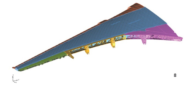
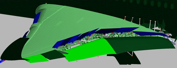
 Finite element model of A350-1000 XWB left wing excluding control surfaces. Image courtesy of Airbus.
The finite element model of the A350-1000 XWB left wing has about 5,000,000 DOF, which was reduced to about 1,000 DOF in the MBS flexible body. The MBS model includes all the primary and secondary control surfaces as well as the landing gear. All movables and the wing are aerodynamically loaded and all movables can be actuated. This model can be used to show compliance with regulation CS-25 section 683 (b) and also for rigging, pre-shaping and predicting wing cruise shapes. The cruise shape predicted by the model was successfully correlated with wing deformation measurement data from the A350-900 XWB flight test campaign.
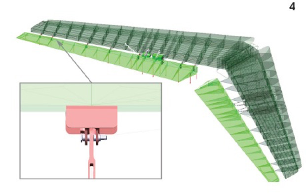
 Multibody simulation model of A350-900 XWB left wing including all control surfaces. Image courtesy of Airbus.
Results
The replacement of the physical A350-1000 wing bending test with simulation of the effects of deflection on the flight controls saved Airbus about $3 million and 4 months on the certification process for the A350,” said Michael Vetter, Project Leader Multi-Body Simulation with Airbus. Most of these savings were achieved by eliminating the need to build test fixtures. Similar savings will be achieved for each future aircraft model. Airbus engineers are also working to apply this same method to other mechanical systems of the aircraft such as landing gear and passenger doors.
This case study was based on an interview with Ulli Landwehr, analyst for Multi-Body Simulation, and Michael Vetter, project leader for Multi-Body Simulation, Airbus.
More Info
Subscribe to our FREE magazine, FREE email newsletters or both!
Latest News


