

Latest News
October 1, 2013
Maybe you design solenoid valves, and need to understand the combined effects of electromagnetic (EM), fluid and structural forces. Perhaps the time-dependent behavior of your mechanical products can be influenced by electrical current flow, so you need to simulate Joule heating. How do you even approach such problems?
Whether div, grad and curl are your best friends, or Maxwell’s equations are a distant memory, you’ll appreciate the surprising ease with which today’s multiphysics (MP) finite element (FE) analysis software packages incorporate EM effects. DE talked to a number of vendors about what’s important for setting up useful simulations.
Who’s on First?
The ever-present drive to make products smaller, cheaper and faster has pushed design simulation software to broaden its MP capabilities. Historically, most such simulation software first combined structural, thermal and fluid behavior, then incorporated EM effects. One exception is Opera-3d software from Cobham Vector Fields Simulation Software, whose efforts started with the EM side.
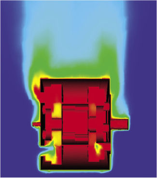
The co-simulation functionality of Abaqus 6.13 from SIMULIA, Dassault Systemes enables the coupling of different disciplines—as shown in this example of the induction-heated fuser in a printer. Understanding temperature distribution and temperature rise time of fusing rollers is critical for energy-saving considerations. Shown in the figure are contour plots of roller temperature distribution, a little after one half and one full rotation(s). Image courtesy of SIMULIA, Dassault Systemes. |
Although EM simulations generally rely on FE for solutions, some also employ boundary element modeling (BEM); a useful characteristic is they can interface with both mesh-based physics and 1D physics such as multi-body dynamics and controls.
Performing an MP analysis that includes EM effects is, in many ways, no different than any other MP simulation task. Dr. Pierre L’Eplattenier, a senior scientist for LSTC, lays out the steps for LS-DYNA users interested in its EM capabilities: “Give the materials an electrical conductivity, give the time steps you want, and define a source electrical field (AC) or time-dependent DC field.”
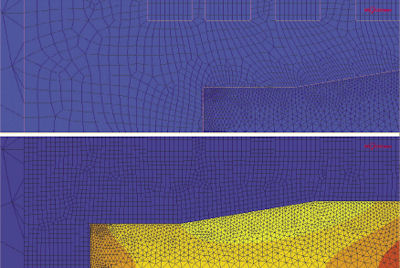
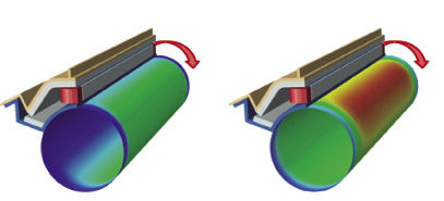
A tube is pushed through a heating coil, and a coupled magnetodynamic thermal structural analysis is performed in MSC Software’s MARC. The harmonic magnetodynamic field generates induction currents in the axi-symmetric workpiece. From these induced currents, a heat flux is computed, which is used in the thermal analysis. The staggered sequence is repeated until the end of the analysis. Single or dual-mesh approaches can be used to handle the solid-to-air interface, and the process can also be conducted in reverse. Image courtesy of MSC Software. |
For best accuracy, LS-DYNA’s computations are FE-based in the electrical conductor, and BEM-based for the mesh in the fluid or air surrounding the conductor.
Vendors are quite encouraging about designers taking on this task, even when new to MP. Dr. Valerio Marra, COMSOL’s technical marketing manager, says, “Usually, setting up the EM problem is easier and quite unambiguous. Adding thermal and mechanical effects can be difficult; that’s when things can get arbitrarily more complicated.”
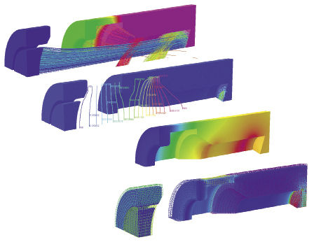
MP analysis of an electron gun performed with Opera-3d from Cobham Vector Fields Simulation Software. Top to bottom: Surface potential and trajectories; potential map and volumetric power density; temperature distribution; and thermal expansion, demonstrating the inclusion of EM, thermal and structural analyses. Image courtesy of Cobham Vector Fields Simulation Software. |
Part of the process requires you to decide whether a sequential or a co-simulated approach is needed, by determining whether the different solutions both influence each other. An example of a sequential approach is running an EM simulation to calculate heat loss, then handing over such parameters as heat flux to a computational fluid dynamics (CFD) solver, which subsequently calculates convection behavior.
By contrast, Jon Quigley, Altair Engineering’s director of multidisciplinary simulation, notes, “In the co-simulation case, both the EM solver and the other solver (which can be mechanical, thermal or fluid) trade data as time moves forward. This can be complicated to set up, due to additional More Information needed, but software packages continue to improve the ease of use.”
One possible challenge: The time periods of interest may vary greatly between domains. For example, a thermal response may ramp up much more slowly (on a scale of minutes) than that of a mechanical (rotating) or electrical (AC) cycle operation. For such cases, designers can time-average losses, then convert them to temperatures as desired.
Choosing to use the same mesh or different meshes across the regions can also involve tradeoffs of computational time vs. accuracy. Today’s packages generally have advanced algorithms that automatically map different meshes to each other as the simulation progresses.
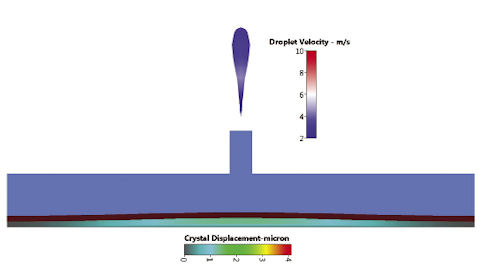
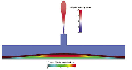
| Inkjet printer-head operation simulated with the ACE+ Suite of simulation and optimization software from ESI Group. When voltage in alternating current (VAC) is applied to a piezoelectric crystal, the material physically changes shape and pushes out a droplet of ink. On this scale, the effect of gravity is negligible; therefore, this configuration shows the drop rising. Images courtesy of ESI Group. |
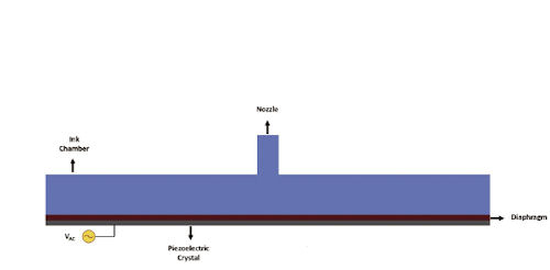
Schematic, piezoelectric inkjet printhead |
Droplet ejection for VAC = 200V; slower, shorter drops |
Droplet ejection for VAC = 300V; faster, longer drops |
Scott Stanton, ANSYS’ technical director for advanced technology initiatives, explains how this can apply when designing a rotor/stator configuration: “You have a fine mesh at the edges of the stator, where the gradient is the largest, but for the thermal part, the heat is all the way across. What ANSYS Workbench does is recalculate the mesh from one to the other, handling the mesh interactions underneath.” Automated check-sums that the user can see compare results across the mesh and allow manual changes, he adds.
Another checklist task for adding (or starting with) EM effects is defining the frequency domain of interest. Most MP activity is in the low-frequency arena, perhaps up to 100 MHz. Applications include actuators, motors, generators and circuits. High frequencies generally refer to microwave operation, such as for antenna and radar designs, or microwave ovens. Analysis of these latter designs is more complex because it cannot neglect EM field components and must solve the full wave equation.
Joule heating in an electric motor. JMAG’s JSOL solution was applied to the electromagnetic design to compute the Joule heat loss; heat flux values were then coupled sequentially to Altair Engineering’s AcuSolve CFD code for designing a convective cooling solution. Image courtesy of Altair Engineering. |
Not all MP simulations handle the full-frequency cases, but this capability is a particular strength of AMPS Technologies Co., the developer of the Advanced Multi-physics Simulation (AMPs) non-linear analysis programs. The company was founded to address tough problems, beginning with fluid-structure interactions and adding EM effects in 2004.
Dr. Ted Lin, a product developer at AMPS Technologies, says that for crucial applications, it’s important to include all the frequency terms when solving Maxwell’s equations. AMPS always includes them, using a strain-rate (edge-type) continuum formulation and a consistent least-squares based method for all governing differential equations.
“We have all the physics on one equal interpolation function, tightly integrated,” Lin says. “Everything converges to a better solution.”
Convergence can be an issue, particularly if non-linear behavior kicks in. ADINA software employs a unified MP system to handle such effects as Joule heating and Lorentz forces along with mechanical and fluid variations, maintaining efficient solution convergence; it can also include Eddy current plus time-varying and high-frequency operation. See the company’s website for interesting, detailed animations of microwave pasteurization and oven processes, for example.
MSC Software’s MARC was developed specifically to incorporate non-linear behavior, and offers two ways to do so while including EM effects. According to Srinivas Reddy, MSC Software’s senior product marketing manager, strongly coupled analyses are more accurate—but they can take more resources and be harder to get to converge. Users might find that a staggered approach works better if there are drastic material property changes. For example, current generation caused by piezoelectric behavior is strongly coupled, but use of the corresponding coupled solver takes lots of resources and may have difficulty converging. MARC can instead take a staggered approach with separate solutions for each time step, and results traded back and forth.
Material Concerns
As with any MP analysis, the biggest challenge can be obtaining the required input data. In the EM world, material properties can be both anisotropic and frequency-dependent, particularly related to skin depth. In addition, swept-frequency behavior can be quite unknown. An example where this becomes critical in the real world is with motor design: It can lose power as the temperature goes up because the material properties are changing. Simulation must take this into account.
“You may have material properties at a single testing temperature whereas multiphysics allows for temperature-dependent material properties to be used,” Dr. Nigel Atkinson, in sales and marketing for Cobham, explains. He adds that this is especially important for rare earth materials, which his company’s Opera-3d software has been designed to handle; typical applications include magnetic resonance imaging (MRI) magnets, particle accelerators, loudspeakers and sputter-coating equipment.
COMSOL’s Marra gives another example where material knowledge is critical: designing an optical fiber. “The EM side of the design problem just needs the dielectric properties, but what about when it bends? The stresses and strains change the optical properties, so the performance is quite sensitive on the structural side.” He adds that many dielectric materials expand, given thermal stresses. Building the correct thermal model depends on understanding the influence of surface finish and contact pressure during operation at different frequencies and signal intensities, all of which determine performance.
Beyond Analysis, to Optimization
Atkinson notes that simulation is best employed when taken to the next step: optimization.
“Products need to be more robust, even though they are placed in more hostile environments,” he says. “This is to be achieved with designs that are more innovative than their predecessors. For example, electrical generators might traditionally have been found mainly in turbine halls in power stations, where operating conditions were controlled and predictable. Nowadays, you see generators in many varied environments, from the top of wind turbine towers to hybrid cars. Designers cannot look at the electromagnetic performance in isolation; they need to consider temperature and mechanical effects to achieve an optimal, but robust design.”
ANSYS Workbench provides an environment that can access best-in-class single physics solvers and integrate their solutions. Image courtesy of ANSYS. |
At ANSYS, the Design Explorer tool lets users try out various combinations of physical parameters for simulations throughout the possible design space. For example, the amount of torque produced by an induction motor is determined by how strongly the magnetic fields of the rotor and stator interact with each other. Give the thickness, outside diameter and material properties of the permanent magnets, the software performs a sensitivity analysis, showing which parameter changes the torque the most.
The sheer number of variables involved in an EM/MP analysis suggests that a hierarchy of prioritization is indeed important.
“Loads—for example, electrical current density on the EM side—are the easiest to optimize,” notes Dr. Krishna Gundu, engineering specialist at SIMULIA for Dassault Systemes. “Geometric parameters can also be optimized, but it involves a little bit more work.”
At press time, SIMULIA is writing a tech brief that describes the tradeoffs made between temperature distribution and mechanical design for an induction-heated printer-roller mechanism, given an overall goal of energy savings.
An interesting optimization example comes from Kunal Jain, product manager for the ACE+ suite of analysis tools at ESI Group. “Most engineers want to improve the efficiency and minimize the size and weight of a device,” he explains, offering drop-on-demand (DOD) inkjet printing technology as an example. “With DOD, individual drops are ejected only when needed. The underlying actuator mechanism can be piezoelectric or thermal, with piezoelectric becoming more popular since it works with a wide range of inks. In the piezoelectric DOD, the voltage pulse excites the piezoelectric element, which changes shape, forcing a droplet of ink from the nozzle.”
Regarding optimization, Jain notes that “producing superior image quality requires small drop size and volume, precise drop shape and fast ejection speed. Amongst the various parameters that the design engineer can control include voltage signal, frequency, nozzle shape, material characteristics, and surface tension of the ink. However, an optimal design requires understanding the underlying phenomena such as surface tension, electrokinetics, fluid-structure interaction and multiphase flows, among others. CFD/multiphysics simulation tools can play a pivotal role in understanding the various complex phenomena, leading to faster, robust, cost-efficient design and optimization of these devices.”
Altair’s Quigley says that optimization goes right to the “DNA” of his company. “On the structural side, back even in the ’90s, we saw that (simulation) goes beyond just getting the answers, but also putting automation on top of that, to be able to have the computers iterate the designs.”
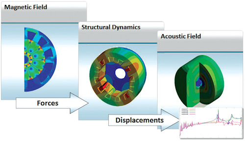
Multiphysics introduces a new dimension to that, Quigley adds, “because if you have some form of coupled simulation, the optimization can wrap around the entire coupled calculations.” The company has just announced a new Altair Partner Alliance with JSOL to offer the low-frequency electromechanical analysis tool JMAG, as a complement to its partnership with EM Software & Systems and that company’s high-frequency FEKO package.
With examples like these, it’s clear that industry is moving beyond basic design and analysis toolkits. Whether you need an MP package that handles low or high frequencies, hysteresis, semiconductor materials or piezoelectric devices, now is a great time to add EM capabilities to your simulation and optimization projects.
Contributing Editor Pamela Waterman, DE’s simulation expert, is an electrical engineer and freelance technical writer based in Arizona. You can send her e-mail to [email protected].
More Info
Subscribe to our FREE magazine, FREE email newsletters or both!
Latest News
About the Author
Pamela Waterman worked as Digital Engineering’s contributing editor for two decades. Contact her via .(JavaScript must be enabled to view this email address).
Follow DE

