Altair SIMSOLID Walkthrough
For this overview, Tony Abbey says he was was able to explore design configurations very rapidly—and this prompted further exploration into alternative configurations such as an integral fitting.
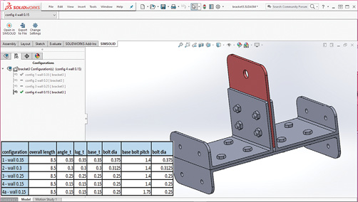
Fig. 1: The bracket assembly with configurations described in the inset. Images courtesy of Tony Abbey.

June 1, 2019
Editor’s Note: Tony Abbey provides live e-Learning courses, FEA consulting and mentoring. Contact [email protected] for details, or visit his website at fetraining.net.
For this walkthrough, I’m looking at another finite element analysis (FEA) software product. I recently described the background to Altair SIMSOLID and its technology in an article on meshless FEA methods (DE, January 2019). SIMSOLID uses the complete geometric domain to define the displacement response. There is no subdivision into the traditional elements. The solver adapts by increasing the number of internal calculation points until convergence of the displacement boundary conditions is reached.
The imported geometry is converted to a faceted representation with an internal geometric hierarchy. The geometry is evaluated for specific feature types such as bolts, thin shells, etc. Interfaces between parts are evaluated for potential contact surfaces. No supporting mesh is used, so the usual FEA focus on adequate mesh control is bypassed.
The results are shown by mapping onto a “display” mesh, using the analytical approximations inherent in the solution. Reaction forces are monitored for convergence. The user can adjust the level of internal points and the number of adaptive passes.
Benchmarking has shown good accuracy for difficult structural configurations such as the “Raasch Hook,” as described in the previous article.
Importing the Bracket Assembly
A bracket assembly has been created in SolidWorks in preparation for this review and is shown in Fig. 1.
Two channel sections are bolted back to back, sandwiching a vertical lug. The channels are bolted to a backing structure (not shown) at either end. A base plate is bolted below the channels and lug, with flanges that abut the backing structure. There are eight bolts connecting the base plate and channel sections. Four bolts connect the channels and lug.
Five geometric configurations have been created in SolidWorks, as shown in the inset table in Fig. 1. The wall thicknesses of the channels, base and lug are stepped through 0.15, 0.25, 0.3 and 0.35 in. The bolt diameters vary between 1/4 , 5/16 and 3/8 in. The last configuration, 4a, has a larger bolt pitch on the base plate, to position the bolts closer to the lug loading plane.
There are two options when working with SIMSOLID. A new SIMSOLID project can be opened independently and CAD geometry can be imported into the project. This would be the normal mode of working independently of CAD. Alternatively, SIMSOLID can be used in embedded mode with several CAD programs, including Autodesk Fusion360, Onshape and SolidWorks. For this review I have used the SolidWorks Add-In. Fig. 1 shows the SIMSOLID tab open within SolidWorks. An icon click here allows the geometry to be opened simultaneously in a new or existing SIMSOLID project. It is effectively a “push” from SolidWorks to a parallel SIMSOLID project. I found this a very convenient way to work; as each configuration is created it is sent to an open SIMSOLID project, where the structural analyses are then carried out. Having two screens is useful when using the simultaneous workflow.
On importing geometry into an empty SIMSOLID project, a Baseline Design Study is created with an Assembly containing all the associated parts. Any subsequent CAD geometry import creates a new Design Study. Each Design Study could potentially have a completely independent set of parts within its Assembly definition. Alternatively, Design Studies can be copied, and parts suppressed, or new external CAD parts can be imported into that Design Study Assembly. This allows great versatility in mixing and matching configurations; you are not limited to “formal” CAD assembly builds.
A very useful feature is the handling of geometry imported into a new SIMSOLID Design Study. If the underlying geometry matches the current Baseline Design Study, then any existing materials, analysis and connection features associated to that geometry will be cloned into the new Design Study. For example, for the lug, the loaded hole does not change relative position, so the geometric surface, loading value and direction are mapped automatically to the new Design Study. The same applies to the constraints linking the bracket to the backing structure. Incoming geometry is also inspected to see if the existing SIMSOLID Connections and Contact Conditions can be reused. If the geometry is consistent and within a tolerance bound, these are cloned in the new Design Study.
The load case setup and analysis type are also replicated using the Baseline Design Study. I found the most efficient workflow was to create a series of analyses in SIMSOLID for the first configuration, i.e., the Baseline Design Study. This included two linear static analyses to cover a vertical and lateral lug loading, and then two non-linear static analyses with both load cases repeated. This then acts as a template for each SolidWorks configuration imported, saving much tedious repetition. More load cases can be added, or existing ones deleted across Design Studies. Any Design Study can be designated as the Baseline Design Study and hence form the template.
Setting up the Baseline Design Study
Fig. 2 shows the bracket assembly imported into SIMSOLID and the connections and analyses setup.
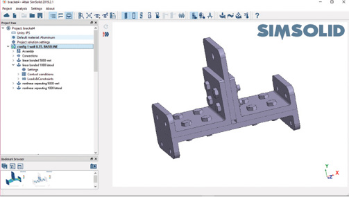
On importing the geometry, each part is assessed by SIMSOLID to identify which category it falls into. Bolts and nut parts require a hexagonal feature and a shank or hole. This means bolts cannot be simplified as purely cylindrical in the CAD model. Washers, springs (not used here) and through holes are also identified. Thin sheet or shell-like bodies are identified and treated differently from general solid bodies. The meshless method behind SIMSOLID can adapt specifically for shell-like topology to ensure good performance through thickness. The user can control the level of adaptivity specifically for thin bodies and individual parts can have enhanced accuracy if needed. However, as a first pass to obtain overall load paths and responses, defaults can be used. Figure 3 shows the Assembly for the Design Study expanded in the Project Tree.
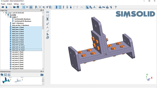
I have highlighted the 12 bolts in the Assembly. The parts categories are shown by the icons and labels. The material allocated within SIMSOLID or inherited from the CAD model is appended to the label. You can toggle between the label given by SIMSOLID or the original part number.
The parts can be checked for geometric errors, contacts, material properties and other features using the Right Mouse Button (RMB) and the Workbench Toolbar. The latter is the vertical menu to the right of the project tree. This menu region is context sensitive and adapts to the project tree level you are accessing. The part attributes such as material and contacts can be manipulated in various ways.
The Contact Connections at this stage are generic—defining contact regions. The Connections can be reviewed by expanding in the Project Tree. The usual method would be to have these generated automatically based on tolerances created on CAD import. Connections can be created manually, edited or deleted using the in-context Workbench Toolbar. Both graphical and tabular editing and review methods are available. I had 65 Connections in the model and found the tools easy to work with. A large assembly could contain many hundreds of connections. Checking and handling these is a realistic prospect in SIMSOLID.
Special connections such as Seam Welds, Spot Welds and Virtual Connectors can also be added from this menu.
The next stage is to set up the analysis. The Main Menu Toolbar is shown in Figs. 2 and 3, spanning the top of the graphics area. The analysis creation icons are here and currently include: Linear Static, Nonlinear Static, Modal (normal modes), Thermal, Transient Dynamics, Frequency Response Dynamics, and Random Response Dynamics. I selected Linear Static analysis.
The Contact Conditions appropriate for linear analysis are automatically created and can be reviewed in the Project Tree. Fig. 4 shows bolt and nut connections created in SIMSOLID.
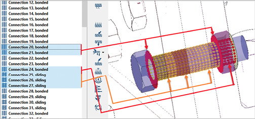
I have added the visualization lines for clarity. The shank of the bolt contacts the three plate sections, consisting of both channels (25, 27) and the lug (26). For linear analysis, these are defined as sliding contacts; no separation is allowed and there is no friction. The contact regions under the bolt head (20) and the nut (21), which bear on the outer faces of the channels, are bonded. The nut is bonded to the bolt shank (24). This is a reasonable linear representation of the behavior of a clamped bolt. The bolt shank cannot “gap,” so bearing load paths and hence local stresses due to shear and bending will be incorrect. The solid bodies (lugs, channels and base plate) are also bonded. However, the primary intention of the linear analysis is to gain some understanding of overall load transfer in large assemblies.
Fig. 5 shows the analysis entities. The connection to ground is defined as a Hinge at each of the bolt hole faces (permitting rotation). The abutting faces are defined as a Slider (sliding in plane). This avoids over-constraining the abutting faces.
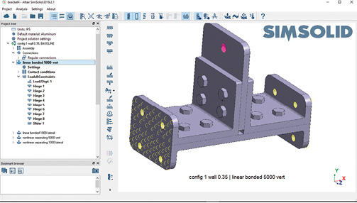
The axial load of 5,000 lbf vertically is applied to the lug.
The Project Tree also shows the other subcases set up in this Design Study: a linear static analysis with a 1,000 lbf lateral load and two non-linear analyses representing the same load cases. Each of these subcases is created by copying the initial subcase and changing the loading and analysis types as appropriate. The analysis type is changed using the Settings object in the Project Tree.
The non-linear analysis can take several forms. If no bolt preload is required then only the bolt to nut needs to maintain a Bonded option; all the other contacts can use the Separating contact option.
If bolt preload is required, then the bolt shank must use a Sliding contact option and the bolt head face and nut face contacts must use Bonded contact. The bolts revert to the linear setup as shown in Fig. 4. However, the solid bodies can use Separating contact. This latter effect improves the overall load path significantly as the bodies can react with a natural “prying” action.
Fig. 6 shows the form used to set up the bolt preload.
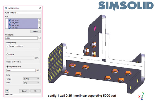
For bolts with nuts, each nut is selected. There are 12 in this assembly. The bolt thread pitch is defined (0.036 in. here). There are three methods available, turning the nut, applying a torque or applying the force directly via a target axial force. I chose the latter with a load of around 80% of the bolt strength. A symbol appears on each nut to indicate preload is applied.
The SIMSOLID bolt preload method uses a different approach from traditional FEA, where a common method is to apply displacement constraint equations to nodes on either side of a split face. This effectively shortens the bolt. Instead, SIMSOLID applies a relative displacement to the bolt shank region at its interface with the nut, stretching the bolt. A vertical shear load is hence transmitted between bolt and nut over this length (the engaged thread length), which balances the bolt axial load. The target axial load is achieved through iteration, as the clamped plates have an arbitrary stiffness. A higher accuracy can be achieved by increasing the adaptive cycles in the analysis from the default value of 3.
Running the Analyses
The analyses can be run one at a time or launched together. In fact, all analyses can be launched across multiple Design Studies, if required. The linear analyses run very fast, even with a high adaptivity setting of 6. The nonlinear analyses take around 2 minutes each on my 4GHz, 32GB RAM Dell workstation. Higher precision can be achieved by increasing the adaptivity level of the analyses. The default 3 can be increased to 9, but 6 is the recommended limit. The analysis run times increase with adaptivity level.
In Fig. 7, the von Mises stress and deformed shape for the vertical nonlinear analysis is shown.
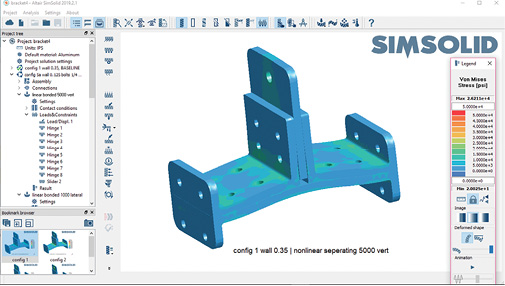
I have set the maximum von Mises stress to 50,000 psi and the minimum to 0 psi to reflect the yield strength of the material. This can be locked across all analysis results using an option on the Results toolbar. The bolts are ghosted in this view. The view can be bookmarked and the Bookmark Browser window is shown in the lower left of the figure. The Bookmarks are a useful record and allow quick snapping between results visualization settings.
The individual bolt loads can be checked as shown in Fig. 8.
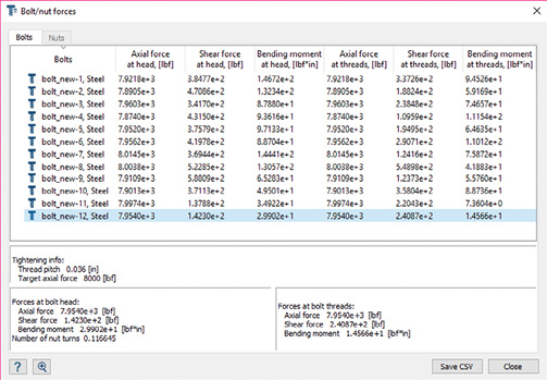
The axial force is very close to the desired 8000 lbf in each bolt. The table can be exported as a .csv file for processing in an external bolt strength calculator.
Fig. 9 shows a free body diagram and table used to investigate how much load is reacted through the base plate, compared to the channels.
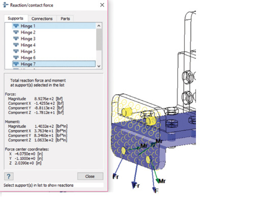
In the figure I have selected, two Hinges form the left-hand connection between the base plate and ground. The combined vertical (Y) reaction is 881 lbf. The two-channel Hinge reactions above this was also checked, and the load ratio is 881/1619 for the base plate and channel per side. The base plate is inefficient as a load path. This result led to later investigations into configurations that do not have a base plate. The free-body and bolt load tools illustrate the SIMSOLID focus on quick overall assessment of assembly load paths for redesign.
At this point, the other CAD configurations are ready to be loaded from SolidWorks. Each of these inherits the contact and analysis settings in the Baseline Design Study when creating the new Design Studies.
Fig. 10 shows the montage of non-linear analysis vertical loading results for various configurations.
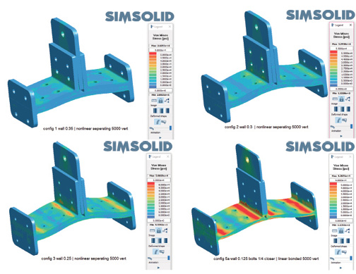
It appears configuration 2, with 0.3 in. walls and 5/16-in. bolts is the best solution. The peak stress in the bracket is just below the 50,000 psi yield for this material. Many further configurations could be quickly explored. I looked at changing the bolt pitch and positioning and further wall and bolt sizes. I also explored removing the base plate and creating an integral fitting. As the geometry strays from the Baseline Design Study, the cloning becomes less effective. However, changing the Baseline to the integral fitting allowed variations in that scheme to be rapidly explored.
Ironically, I spent more time improving my CAD skills than learning the straightforward SIMSOLID interface for this overview! This highlights the linkage between design and analysis that SIMSOLID brings. I was able to explore design configurations very rapidly—and this prompted further exploration into alternative configurations such as an integral fitting.
I also found that SIMSOLID allowed my understanding of the structural load paths to develop. This was an interesting change from the usual focus on detailed stress analysis. The design evolved to a point where it was ready for more detailed strength and stiffness checks—and this is where a more traditional FEA program would take over.
There are several SIMSOLID design-oriented areas I hope to explore in the future such as the seam weld and spot weld capabilities, as well as the shell-like geometry representations.
More Altair Coverage
Subscribe to our FREE magazine, FREE email newsletters or both!
About the Author
Tony Abbey is a consultant analyst with his own company, FETraining. He also works as training manager for NAFEMS, responsible for developing and implementing training classes, including e-learning classes. Send e-mail about this article to [email protected].
Follow DE

