Autodesk Inventor 2008
The latest version of the design program lives up to its name.
The latest version of the design program lives up to its name.
Latest News
AMGTA Shares Findings on Sustainability of Powder and Wire Additive Feedstock
MATLABS Features Modelithics EXEMPLAR Library
Fictiv Demonstrates New AI Capabilities
ADDMAN Earns Qualification Project for U.S. Navy
FREE WEBINAR May 7: Addressing the Skilled Worker Shortage with Customized eLearning
America Makes’ Spring 2024 TRX Explores AM Advancements
All posts
May 1, 2007
By Al Dean
Autodesk’s next release of Inventor, which nicely sidesteps the dreaded R13 designation, has a host of improvements and new features, not the least of which is parity with AutoCAD. Inventor 2008 includes standardized sketching functions with Inventor part modeling so that they look the same (in terms of icons) and operate the same as within AutoCAD.
Inventor 2008 also includes improvements made to constraints management and sketch geometry formatting. Previously, Inventor would display all constraints within a sketch at once, which could get confusing. You can now filter that back to just show the most critical constraints. Elsewhere, you now have full control over sketch formatting in terms of line type, color, weight, etc.

Inventor 2008 also includes improvements made to constraints management and sketch geometry formatting. Previously, Inventor would display all constraints within a sketch at once, which could get confusing. You can now filter that back to just show the most critical constraints. Elsewhere, you now have full control over sketch formatting in terms of line type, color, weight, etc.

Inventor 2008 offers enhancements and additions that flesh out Autodesk’s functional design capabilities and bring parity between Inventor and AutoCAD to assist with knowledge reuse.
The 2008 release cycle features the introduction of DWG TrueConnect. This allows more intelligent use of DWG data in the various incarnations of AutoCAD and Inventor. Within Inventor, you can now choose to store your draft data as a .DWG file rather than the existing .IDW file, but the real key is the ability to share information among Autodesk applications.
Within Inventor, you can open an AutoCAD DWG, extract view information, blocks, etc., and reuse that data. Or, if you’re working with AutoCAD, you can access an Inventor-generated DWG file and mark up or annotate Inventor drawing views to create the documents you require. What’s important to note is that the DWG files can only be edited by the originating system, which makes sense in terms of design changes control. While we’re on the data-exchange issue, data can be moved between Inventor and AliasStudio products, making for a more efficient workflow.
Elsewhere, the user experience is updated with a redesign of icons and Windows XP-type control icons. New User Profiles allow you to store your UI layout (such as toolbar position, custom toolbars, etc.) and load it — handy for those working with multiple users using different workstations. Also on the productivity front, this release includes the introduction of command aliases.
Sheet Metal
Sheet metal is always a core concentration for any vendor as there is a real need to be able to define the sheet metal form intelligently in both 3D and 2D. In general terms, the big sheet metal update here is that you now have separate browser trees for folded and unfolded model (allowing you to have both open at the same time), and you can now add features to the flat pattern. The new contour flange allows you to wrap a profile down multiple edges on a part within a single feature, with automatic mitering, making the history tree and design modifications much easier. Punch support now allows you to store standard punches in a library, which can be dragged and dropped into your model and reused just as you would any standard iFeature. The system holds two representations of the punch; a full 3D representation, and also a 2D sketch of the punch in the flat pattern for documentation purposes.
Taking the documentation and manufacturing preparation step further, you can now extract much more information within a 2D drawing. When you create the views as normal, you can also bring across the forming information (such as bends, punches, locations, etc.) and extract the markups or annotation for those features. So, bend lines are automatically created and hold information about the actual bend (i.e., down 76 degrees). You can also create bend tables that allow you to tabulate the bend angle information into a table and link those bend details to numbered bend lines on each view. The same holds true for creating a punch table, but these hold Punch ID, angle (of rotation), depth, and positioning coordinates. Finally, Inventor Professional users can now conduct stress analysis work on sheet metal models, as sheet elements have been added to make it more efficient.
Shape & Assembly Design
Let’s take a quick look at the part and assembly modeling updates. In terms of part and shape description, this release includes a new feature, Area Loft. This is ideal for those working in pneumatics and hydraulics as it allows you to create a basic loft, then scale each section according to the area it represents (rather than explicit dimensions), allowing you to define it by function rather than form.
For those working with frames, you can base a framework on a mix of 3D part edges or using 2D/3D wireframe sketches. End treatments and junctions have been improved and remain persistent through design changes, even if you change section types — and curved sections can now be stored as a single part rather than sections. Finally, if you’re working in a skeleton-driven manner, then updates to top-down driven assemblies are more efficient as the system will only update parts that have changes, rather than tackle the whole thing (as it did previously).
Design Accelerators
Design Accelerators are key to Autodesk’s Functional Modeling concept — and the work accomplished in this release reflects the company’s desire to deliver on its vision of defining a sub-system based on function, and then having the application create the form. The new Shaft and Chain Drive Generators are perfect examples. Everything is done in context, starting with the definition of a shaft. You model the basic shape, and add the various features (relief, blends, keyways, etc.) using references from the assembly to define shape and position.
You then use the calculation tools to derive the correct form according to your performance requirements. The system creates the 3D geometry, places it into position within your assembly, and generates a separate report to document the process (I’d like to see it stored as part of the part tree structure). As you then add components to that shaft, such as drive components, pulleys, bearings, etc., they all adapt and use the information you’ve already defined, automatically mating where appropriate.
The Chain Drive Generator works the same way. You define the gears, chains, and belts according to design intent (using references, with 3D or sketches), carry out strength calculations, choose to restrict chain lengths (to standard sizes); and you can experiment with the configuration. When you have the final form, you have the system build it in 3D. This creates all the parts, mates, and constrains them correctly (so that mechanisms work), and creates the assembly structure — all within a few mouse clicks.
Inventor Professional
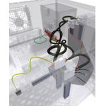
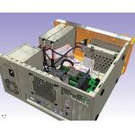
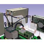
We’ve already discussed the ability to carry out thin wall stress analysis on sheet metal parts, but version 2008 also includes work in other areas. Within Cable and Harnessing, you can now create Ribbon Cables. Connectors are added into position, you create the initial ribbon, route that cable by defining geometry constraints, twisting or folding where necessary. Once complete, you can use the nail-board design tools to document its design and manufacture.
In Dynamic Simulation you can now transfer the assembly constraints already defined within an assembly for motion simulation. You may need to edit these, but you get there quicker than in previous versions. Motion Loads can also be exported for multiple time steps for use in the Stress Analysis tools.
   |
| Inventor 2008 supports the insertion and routing of ribbon cables with full control over the shape of the cable, including the ability to define multiple twists and folds. The images below provide alternative views of the Cable and Harnessing capaibilities in Inventor 2008. |
Finally, the new Imposed Motion condition allows you to define required motion of a component over time (using graph or imported data). If you link this with the new Persistent Trace curve tools, you have the ability to create cams and such things easily by defining the motion you want in terms of output, then have those “driving components” derived automatically — eliminating a lot of the guesswork.
Satisfying a Vision
Inventor was late to market and spent its formative years playing catch-up. That said, the last few releases have shown that the product has reached a level of maturity allowing Autodesk’s team to compete on a pretty level technical playing field.
The drive toward functional design is something I’m watching keenly, and the updates in this release show how it can work. It also illustrates how functional design can be delivered so that it makes a complex process both more efficient and more intelligent by allowing you to integrate more knowledge into the process rather than just 3D modeling. I love the shaft and Chain Drive Generators — they solve engineering issues based on functional inputs rather than arcane geometric dimensions and that’s always a good thing. Elsewhere in this release both the UI work done to pair Inventor with AutoCAD and the introduction of DWG TrueConnect mean you can use your DWG data in the manner you want, sensibly. I’m particularly excited about the potential for the interaction between AliasStudio and Inventor. Yes, this is a stop gap until newer products emerge, but for now, it’s a good workflow for those involved with industrial design.
I think back to when Inventor was initially announced, I remember thinking, “That’s a cool name for a product.” Looking at the system now, I’m starting to think that it’s finally living up to its name. Inventor is gaining competitive advantage through the use of intelligent technology that allows you to invent as you would, from engineering and design principles, rather than cryptic modeling operations, and for that reason alone — I like it a lot.
Al Dean is Technology Editor of the UK’s leading product development and manufacturing journal, MCAD and is Editor of Prototype, for the rapid prototyping and direct manufacturing industry, both available by clicking here. Send your comments about this article through e-mail by clicking here. Please reference “Inventor 2008” in your message.
Contact Info
Inventor 2008
Autodesk, Inc.
San Rafael, CA
Subscribe to our FREE magazine, FREE email newsletters or both!
Join over 90,000 engineering professionals who get fresh engineering news as soon as it is published.
Latest News
AMGTA Shares Findings on Sustainability of Powder and Wire Additive Feedstock
MATLABS Features Modelithics EXEMPLAR Library
Fictiv Demonstrates New AI Capabilities
ADDMAN Earns Qualification Project for U.S. Navy
FREE WEBINAR May 7: Addressing the Skilled Worker Shortage with Customized eLearning
America Makes’ Spring 2024 TRX Explores AM Advancements
All posts
About the Author
DE’s editors contribute news and new product announcements to Digital Engineering.
Press releases may be sent to them via [email protected].
#9500
New & Noteworthy

New & Noteworthy: Safe, Cost-Effective Metal 3D Printing - Anywhere
Desktop Metal’s Studio System offers turnkey metal printing for prototypes and...

New & Noteworthy: Direct Neutronics Analysis on CAD
Coreform Cubit 2023.11 workflows enable neutronics directly on CAD for next-generation nuclear energy...

New & Noteworthy: Agile Engineering Collaboration
Authentise Threads is a new software tool for distributed communications and project...

New & Noteworthy Product Introduction: Enterprise VR Headset
Lenovo ThinkReality VRX has an immersive display works with virtual, augmented and...


