Automated Metrology Benefits
Automated metrology increases throughput and provides greater consistency for industrial processes, but system designers can benefit from it as well.

Latest News
April 1, 2013
In addition to the usually obvious advantages in the manufacturing environment, designers can (and need) to do things differently because of automated metrology. If done properly, benefits can occur in the upfront design process based on implementing automated metrology in manufacturing. The benefits for designers include minimizing design process steps and/or time—resulting in further cost savings to the enterprise.
One example is provided by InnovMetric Software’s new Play Inspection tool. This tool, now fully integrated into Phase II of DirectReplay, released in version 12.1 of PolyWorks, automatically builds a guided step-by-step sequence to capture 3D datasets of a work piece.
“The purpose of the Play Inspection tools is to allow users to easily perform repetitive inspection tasks,” says Marc Soucy, president of InnovMetric Software.
Properly inspecting a part is greatly improved if the designer’s role is taken into account in the workflow. Designers define the geometry, controls and tolerances; measurement planners define the measurement methods, and measurement operators capture 3D data of the physical parts (see Fig. 1).
Designers need to care about the what, the first step. The how is done by the metrology specialists who know how certain projects should be measured. “What we have done in Play Inspection development is automated the third step, the when,” says Soucy.
“When designers incorrectly create their dimensions in ways that cannot be easily measured, they put an additional burden onto the metrology specialist,” he explains. Inadequate communication between the design and manufacturing teams adds to the problem. CAD models need to specify dimensions that can be readily understood and implemented by the metrology specialist.
“A company that wants to streamline its process should build a discussion focus group between the design and manufacturing people, and agree on certain rules,” recommends Soucy.
The geometric dimensioning and tolerancing (GD&T) quality control method for 3D solid models plays a role in the process as well, he says.
“When the CAD people put GD&T in their CAD model, usually that translates very, very well,” says Soucy. Done properly, he notes, the addition significantly accelerates the inspection process. The geometry, controls and tolerances are automatically transferred to the inspection application (see Fig. 2).
Inspection Requirements in the CAD Model
Hexagon Metrology’s 4.5.4 SF shop floor coordinate measuring machine (CMM) adds analog scanning to its capabilities. With an optional LSP-X1c probe head, the unit’s design supports standard probing—including single-point probing—self-centering and continuous high-speed scanning. Shaun Wissner, a PC-DMIS Software marketing specialist for Hexagon Metrology, notes that even though CMMs have been around since the 1960s, until recently, they still required heavy human interaction before, during and after the manufacturing process to conceive, collect and interpret any 3D data going in and coming out.
 Figure 1: Three separate entities perform the what, how and when of part inspection. Image courtesy of InnovMetric Software. |
“We are starting to see manufacturers embracing ideas like model-based definition (MBD), where inspection requirements are added to the CAD model, which eliminates the need for part prints,” says Wissner. Most current CAD/CAM software packages support embedding GD&T and linear tolerancing into native component models. As a result, this saves the CMM planner a critical step of interpreting the designer’s intent for a given measurement requirement.
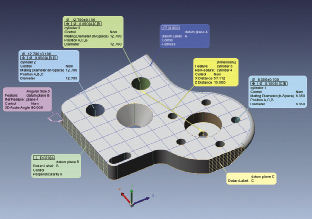 Figure 2: A CAD model with embedded product and manufacturing information provides considerable metrology data when it is opened by an inspection solution such as InnovMetric’s PolyWorks. |
Wissner also observes that offline programming for direct computer controlled (DCC) CMMs is on the rise. While this has long been the standard for computer numerically controlled (CNC) manufacturing equipment, inspection software like Hexagon Metrology’s PC-DMIS Planner is built to take advantage of this new data added to CAD models. This allows users to simply point and click on the GD&T feature control frames and linear dimensions.
“Inspection routines that took hours, or even days of repetitious work are now finished in minutes, as all the necessary features and dimensions are created with the same mouse click,” says Wissner. When complete, the inspection routine is downloaded to the CMM for simple, one-touch execution by any machine operator (see Fig. 3).
The Future is Now
Design engineers use 3D scanners to reverse engineer a physical part to design the tools. As a result, data quality is important, especially in aiding with the associated downstream processes. To scan parts larger than 6 ft. and/or up to about 2 tons in weight, GOM mbH recently introduced the ATOS ScanBox 6130. Similar to previous models, the 6130 is an industrial measuring cell for fully automated 3D digitizing and inspection.
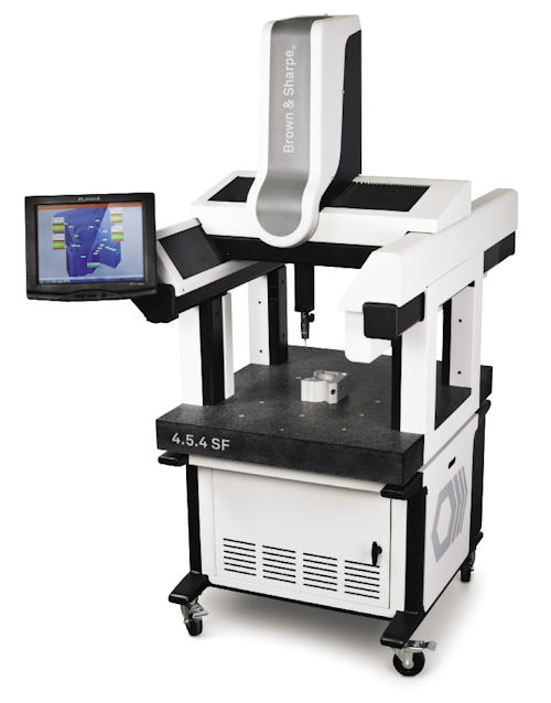 Figure 3: Hexagon Metrology’s 4.5.4 SF CMM is easily transported between required locations in a manufacturing facility. |
An accurate, high-resolution, fast and versatile 3D scanner can be used in product development stages from beginning to end. “Many of our customers have ATOS systems installed throughout design, try-out, and production departments within the same organization,” says Catherine Kim, a marketing coordinator for Capture 3D, the firm representing GOM in the U.S. and Canada.
“The important thing of scanning a part for the design process is, how do you get very accurate, high-fidelity data that will help with the CAD creation changing the design layout—which in essence, saves time and money?” Kim adds. Using a system such as ATOS ScanBox, she says, allows users in aerospace turbine blade and automotive manufacturing operations and others to achieve these savings.
For all the benefits that customers can realize in the manufacturing arena, obtaining benefits earlier in the design process still takes a different approach.
“What needs to be done is improve the ways that designers use the ]product and manufacturing information, or PMI] capability of CAD, so that what they give to manufacturing people is more ready to use,” InnovMetric’s Soucy concludes.
Randy Frank is a contributor to DE. Send e-mail about this article to [email protected].
More Info
Subscribe to our FREE magazine, FREE email newsletters or both!
Latest News
About the Author
Randy FrankRandy Frank is a freelance technology writer based in Arizona. Contact him via [email protected].
Follow DE

