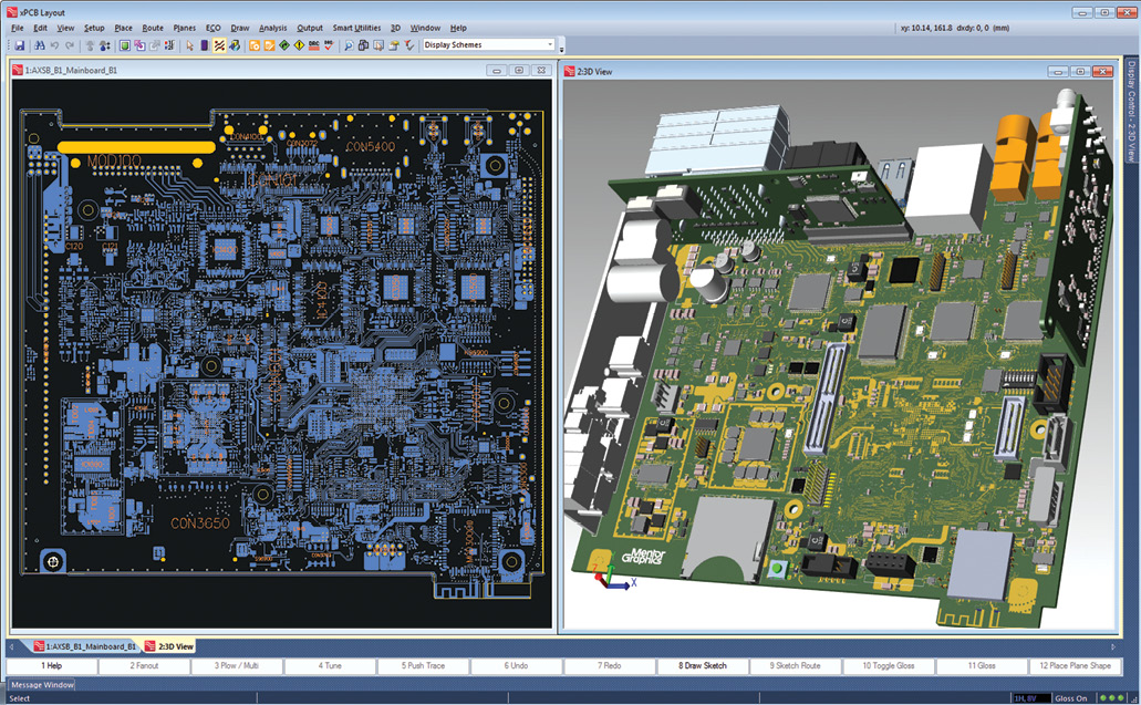
A co-working environment with visibility into changes in MCAD and ECAD design, as exemplified by the solution shown here from Mentor Graphics (recently acquired by Siemens PLM Software), lets mechanical and electrical engineers efficiently collaborate with each other. Image courtesy of Mentor Graphics.


Latest News
May 1, 2017
David Wiens quips that electrical and mechanical design collaboration is sometimes facilitated by “a voice-driven mouse”—one engineer standing over another’s shoulder, issuing instructions about the changes needed. Regarding efficiency, Wiens thinks this method is just as bad as swapping electrical CAD (ECAD) and mechanical CAD (MCAD) files by email.
Wiens is the Xpedition product marketing manager for ECAD developer Mentor Graphics, recently acquired by Siemens PLM Software, a division of the manufacturing giant Siemens AG. Historically a CAD and product lifecycle management (PLM) provider, Siemens PLM Software is bringing an ECAD developer on board in recognition of the growing importance of the electronics in connected devices and IoT commerce.
 A co-working environment with visibility into changes in MCAD and ECAD design, as exemplified by the solution shown here from Mentor Graphics (recently acquired by Siemens PLM Software), lets mechanical and electrical engineers efficiently collaborate with each other. Image courtesy of Mentor Graphics.
Dassault Systèmes, a rival of Siemens PLM in CAD and PLM, recently acquired the electromagnetic and electronic simulation software maker CST. SOLIDWORKS, the division of Dassault Systèmes responsible for the popular SOLIDWORKS MCAD software, struck up a partnership with ECAD maker Altium to develop an MCAD-ECAD interoperability solution, dubbed SOLIDWORKS PCB.
Due to the distinctly different types of geometry each discipline must create, a single modeling package for MCAD and ECAD is unlikely. So the best approach may be to “enable dynamic/concurrent visualization of changes made in ECAD and MCAD environments,” says Wiens.
Bridge Building Between Electrical and Mechanical Engineering
Previously, ECAD meant 2D schematics of printed circuit board (PCB) designs. But today, many ECAD modeling programs have 3D modeling features. These tools are necessary because circuitry and board designs have evolved to include bendable, flexible PCBs and PCB stacks that are difficult (or, some might say, impossible) to represent in 2D drawings. However, many standard 3D mechanical modeling features like surfacing tools, spline tools, sheet metal tools and subdivision modeling tools would be irrelevant to the electrical design discipline. Although they are necessary to produce the smooth surfaces and aesthetically pleasing shapes preferred by industrial designers, they are of little or no use to PCB designers. Therefore, a single consolidated modeling package for both disciplines seems ill-advised. What the two disciplines need is a bridge—a 3D visual environment where MCAD and ECAD models can come together for collision and clash detections.
“Naturally, users prefer to work in their own respective ECAD and MCAD software. However, there are strong reasons for the design to be fully available and also interoperable for other downstream processes and use cases, be that for supplier work-in-progress or final manufacture,” says Annalise Suzuki, director of technology and engagement, Elysium. Elysium develops interoperability solutions for digital design and product lifecycle management (PLM) markets. Its products focus on translating, repairing and ensuring product data quality for 3D CAD/CAM and CAE models.
“ECAD and MCAD are very different systems and work to integrate them is still in progress. This will be challenging; in addition to software integration there are the issues between two completely separate teams/cultures/architectures,” says Alexander Christ, technical expert, Elysium.
“Today’s ECAD and MCAD engineers/designers typically prefer to work in their own respective environments, mostly because there have not been any other alternatives,” says Linda Mazzitelli, PTC’s segment solution director for PLM. “These collaborative design environments currently rely on the exchange of a data file between them to ensure alignment.
Once a CAD and PLM company, PTC transformed itself in the last decade into an IoT technology provider. A milestone in its metamorphosis was the 2014 acquisition of ThingWorx, which offers a platform to develop applications for connected devices. Prior to that, in 2011 PTC acquired MKS, which provides software lifecycle management solutions.
PTC also offers the PTC Creo MCAD-ECAD Collaboration Extension, a module based on the company’s own proprietary technology. The add-on component allows MCAD and ECAD users to see each other’s updates at the geometry level.
“Mentor Graphics and Siemens PLM currently leverage 3D information between each other,” says Joe Bohman, senior VP of lifecycle collaboration software, Siemens PLM Software. “We will continue to enhance the customer business process between mechanical and electrical so that cross-domain decisions can be made quickly and easily.”
The Impact of IoT
Traditionally, MCAD and ECAD users collaborate by setting up clear boundaries: While working on the housing or shape of the product, the MCAD user leaves sufficient room for the anticipated electronics, circuitry and PCBs in the design. The ECAD users design their components within the prescribed specification so the completed work can fit snugly into the housing. This approach may still work with larger assemblies (household appliances, for example).
However, with connected devices for the IoT era, the interdependencies between the outer shape and inner electronics make the traditional approach inefficient. In a mobile tablet or a smart watch, for example, any changes made to the outer shape is bound to alter the location and orientation of the inner circuitry, battery and PCB layout. Conversely, even slight repositioning of the inner components would need to be accommodated by modifications in the housing; hence, the need for an MCAD-ECAD co-working environment.
“Mechanical drives electrical most of the time,” notes Christ. “In long-term projects, it is assumed that electrical will make last-minute changes due to the faster evolution of electronics ... Mechanical designers are limited by the material properties of the structural ingredients, hence the shape is determined by performance requirements leading to specific material, and/or design constraints that are hard to change. The challenge is to allow for last-minute electrical changes. More cables, more sensors, changing size of sensors, motors, actuators, etc.”
The design collaboration, or problem solving, usually occurs at the interfaces of the ECAD and MCAD envelopes, says Suzuki. “MCAD and industrial modelers are increasingly bidirectional and are helped by interoperability and healing solutions that resolve issues over inexact geometry and data transfer,” she observes.
“Most times the form is first proposed by the mechanical team,” says Wiens. “But that doesn’t diminish the contribution of the ECAD team to the decision, since they must determine the function within the form, considering options for layer stack-ups, IC packaging, rigid/flex, embedded devices ... Regardless of who starts first, there is inevitably iteration to reach the optimal solution.”
In most cases, MCAD defines the board size, shape, holes, slots, keep out areas and electro-mechanical component locations, Mazzitelli says, that is, anything that needs to interact with the outside world/enclosure and overall product structure. “Negotiations do occur regarding those predefined items in order to fit everything within the confines of that footprint; however, as long as there is flexibility regarding the mechanical constraints, they are often easily resolved,” she says.
Beyond Electromechanical
System simulation has traditionally been defined by the needs of the OEMs (original equipment manufacturers). Therefore, by and large, its protocols and processes are manufacturing-centric. However, with the likes of Google and Apple dipping their toes into manufacturing with self-driving car concepts, system simulation may take on new flavors.
“Depending on the industry you are dealing with, processes, systems and expertise may vary,” says Christ. “Think about building a car. An established automotive OEM like Ford integrating ICT (information and communication technology) into their cars for connectivity and communications will take one approach. With high expertise in ICT but less experience in engineering, someone like Apple building and developing a connected car will take a different approach.”
CAD and PLM vendors’ expansion of their portfolios, often by acquisition, suggests they recognize the need to be able to offer a comprehensive collection of tools to address the convergence of modeling (electrical and mechanical), simulation, software development and even sensor-collected data from connected devices.
“IoT is all about collaboration and communication in an interdisciplinary environment. Besides ECAD and MCAD for modeling and simulation, you need to integrate solutions from ICT,” says Christ. “We need to start developing interoperability solutions that extend our ECAD/MCAD systems that we are using today with functionalities that allow the development, simulation and validation of all these upcoming challenges.”
“Siemens PLM and Mentor Graphics jointly view software-in-the-loop as a key to enabling our customers to quickly get to market with first-time production of products that combine electrical, software and mechanical,” says Bohman. “Of course IoT will have many products that will fit this profile. We see our combination as enabling simulation of these products as a need based on the increase in product complexity and the rapid expansion of IoT.”
“Some ECAD and MCAD vendors provide hardware and system simulation products. However, at least on the ECAD side, they are not yet at the stage where they incorporate IoT as a part of those,” says Mazzitelli. “Creo has a lead in enabling digital twin emulation, but ECAD currently remains behind in this area.”
With a portfolio that addresses IoT apps development, software development and electromechanical collaboration, PTC continues to champion the “digital twin” concept—connecting digital prototypes to real-world products with sensor-collected field data. (For more information, read “Driving Toward Digital Twins,” or watch the on-demand webcast “Breathing Life into Digital Twins.”
More Info
Subscribe to our FREE magazine, FREE email newsletters or both!
Latest News
About the Author
Kenneth Wong is Digital Engineering’s resident blogger and senior editor. Email him at [email protected] or share your thoughts on this article at digitaleng.news/facebook.
Follow DE

