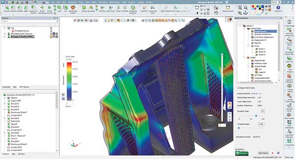
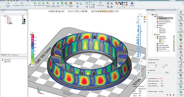
The ability to simulate what happens to the part during the print process, as shown here in examples from 3DXpert, prevents print job failures. Images courtesy of 3D Systems.


Latest News
April 15, 2020
Advanced CAD users have lamented that some complex surfaces and shapes they could model with their software could not be manufactured due to the limitations of production technologies. However, the advances in additive manufacturing (AM) or 3D printing flipped the situation. Many CAD users found out their software couldn’t digitally model the complex shapes AM hardware is itching to print.
Classic parametric modelers were developed to produce geometry suited for machine shops. But AM is capable of so much more. It can produce lattice fills, membrane-like structures and swirling geometry—nicknamed alien topology by some—the kind few will attempt to fabricate using machining.
To fill the gap, some AM hardware makers, such as Desktop Metal and 3D Systems, developed their own software. CAD vendors simultaneously sought out acquisitions and partnerships.
In late 2018, PTC paid $70 million to buy Frustum, a startup with generative design technology. Frustum could let PTC users “create complex geometries optimized for additive manufacturing and deliver better products faster,” points out Jesse Coors-Blankenship, founder of Frustum and senior VP of technology at PTC.
Furthermore, he notes, “With generative, engineers can take advantage of advanced manufacturing techniques and embrace additive manufacturing.”
In 2017, manufacturing and design software maker Siemens struck up a partnership with Materialise, an AM software developer. The goal is to integrate “AM technology from Materialise into Siemens’ NX software, streamlining the design-to-manufacturing process for the rapidly growing universe of products being produced using AM,” the press announcement stated.
These mergers and alliances are indicators of design and manufacturing software jointly tackling AM challenges that each sector is unequipped to tackle on its own.
Print Simulation is Complex
CAD developers are generally not in the best position to write full-fledged AM software—particularly, print preparation software. Their coders do not thoroughly know what happens to materials when they go through the printing process.
“You could use the empirical approach. You can print out a few specimens, measure the shrinkage and warpage in the results, then calibrate the production runs based on this knowledge,” says Maoz Barkai, product manager for 3DXpert, 3D Systems.
But a better tactic is a computer simulation-driven approach. “You simulate what will happen in the print process, down to the micron level,” he says. This allows the design engineer to understand the inevitable warpage and shrinkage that occurs in the print process, so they can then adjust the geometry to compensate for these effects in advance.
“There are more things you can do with plastic printing to compensate for the anticipated morphing or to fix it post-printing, but metal is much less forgiving,” Barkai says. “The harder the metal, the less forgiving it is. So printing in titanium, for example, gives you less room to work with than aluminum.”
3DXpert uses the Amphyon simulation kernel, developed by Additive Works. The same kernel is also used by Altair in its AM-targeted products. Described as “end-to-end fault prediction,” 3DXpert allows users to analyze and determine part orientation for the print job, design lattice fills and add support structures.
The software keeps the original CAD file’s “B-rep data (solids and surfaces) without downgrading to mesh [and] maintain data integrity, including analytic geometry, part topology and color-coding,” according to 3D Systems.
At SolidWorks World in February 2018, 3D printer maker Desktop Metal introduced its generative design software, dubbed Live Parts. It was a software borne out of necessity. The hardware maker felt existing modeling tools didn’t meet the design needs of its hardware users, and was prompted to develop its own offering.
“We feel it’s important that such tools are integrated into the manufacturing processes. You have to design a part that not only looks good but is also be a good candidate for 3D printing,” says Andy Roberts, VP of software for Desktop Metal.
As the name suggests, Desktop Metal focuses primarily on metal-based 3D printing. In addition to Live Parts, the company also offers Fabricate, model-preparation software and Fab Flow, print job management software for fabrication shops.
“We spent quite a bit of time developing software that lets you simulate what happens in the print process and the sintering process. We are integrating both design rules and manufacturing rules in Live Parts, so you can force the software to generate parts that need no internal support or reduce supports to only what’s absolutely necessary based on orientation,” notes Roberts.
Scaling a part to account for distortion in printing isn’t as simple as enlarging a part uniformly by a certain factor. “The Z-direction shrinkage is subject to gravity and material compression,” notes Roberts. “You also need to deal with creating supports that can be removed.”
Desktop Metal developed a patented technology to create easily removable support structures. “The ceramic-like connections turn to dust when you sinter the part, so they can be removed like puzzle pieces by hand afterwards,” explains Roberts.
Multiphysics Phenomena
With some print processes, the simulation software may need to account for more than one type of physics to accurately mimic what happens to the materials. “The simplest example is the combined heat transfer and structural analysis,” notes Bjorn Sjodin, VP of product management, COMSOL.
Using COMSOL software’s Application Builder function, UK-based The Manufacturing Technology Centre developed an app to simulate shaped metal deposition.
According to Borja Lazaro Toralles, MTC’s technology manager, the process involves “molten metal […] deposited layer-by-layer on a surface, allowing for use of multiple materials on one part. However, due to the intense heat of the metal, the final piece can deform during printing.”
“The solidification of molten metal may include fluid flow, heat transfer and maybe even transport of chemical species,” Sjodin points out. Multiphysics simulation also may be required to recreate the behaviors of DC or AC electric currents, magnetic fields or microwaves in AM, he adds.
COMSOL Multiphysics 5.5, released in November 2019, includes improvements to export smooth geometry from topology optimization results.
“Such smooth geometry output from COMSOL can then be used in CAD software or dedicated software tools for preparing for AM,” Sjodin points out.
The software also includes a metal processing module for analyzing metallurgical phase transformations in materials such as steel and cast iron. “I believe this product will also be of interest to AM in some cases since such phase transformation also occurs in AM in unexpected manners,” says Sjodin.
CAD Geometry vs. Print Geometry
CAD geometry is the shape of the desired part. By contrast, print geometry is the geometry destined to be produced in a 3D printing machine. The two often have slight or significant differences. For example, the CAD geometry of a bracket is different from the print geometry, which involves the shape of the bracket and the support structures necessary to keep it propped up during the print process.
The transformation from CAD geometry to print geometry usually occurs during the simulation phase or the print prep phase. This is where the manufacturing engineer adjusts the geometry to account for the anticipated distortion and adds the required support structures.
“It is more important to have detailed information on the build job, which can be different from the CAD geometry,” says Manuel Michiels, market innovation manager at Materialise. “You want to simulate the behavior of the machine and hence the machine input, including things like support geometries and the real process parameters. These are required in order to simulate the creation of the parts accurately.”
Materialise offers Magics software, a model preparation and STL editor for AM. Despite shortcomings, the STL format remains a robust format for common types of AM jobs, Michiels points out.
“It’s capable of describing any type of geometry. It’s straightforward to correct geometries into watertight geometries and currently offers compatibilities with most other software solutions,” he says.
To augment STL’s capabilities, Magics software also retains the color information and uses parametric data—things the file format cannot do.
The Journey of the Part
The typical path from CAD geometry to printed part goes as follows: “It starts with CAD, then build planning (e.g., Materialise), and then simulation (e.g., Simufact Additive). In this workflow, the value of using CAD data would be lost because the build planning software is generally only able to export models in STL. There is a need to develop enhanced 3D data formats, which can maintain fidelity of the original CAD,” outlines Jeff Robertson, technical business development at Simufact, part of Hexagon.
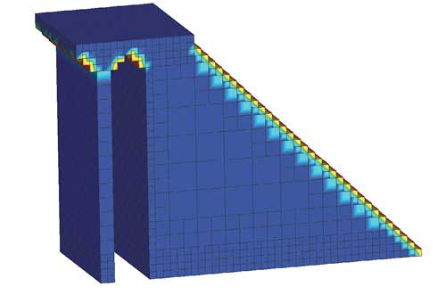
Hexagon’s Simufact Additive 2020 uses adaptive meshing technology to retain the original’s CAD model in fine details shown here. Image courtesy of Hexagon.
STL, which stands for stereolithography, uses triangles to depict geometry. Therefore, converting the mathematically precise CAD geometry into STL means using approximations for rounded corners, fine details and complex surfaces. Furthermore, it cannot describe colors. Recently, 3MF, managed by the 3MF Consortium, emerged as a new format to compete with STL.
“There are meshing techniques like voxel meshing that can automatically mesh any geometry fast and reliably without any user interaction. Also, smaller features can be represented well with approaches like volume fraction consideration and adaptive meshing, made as available in Simufact Additive,” notes Robertson. “It is also possible to export distortion-compensated geometries in generic CAD formats so they can be fed back into the digital workflow without losing feature information of the part.”
STL’s Challenger
Materialise’s Michiels believes a tight link between AM software and CAD formats would be a blessing. “We are taking appropriate actions to also allow our customers to get the best out of both worlds. This started many years ago by describing lattice structures in a parametric way instead of in STL,” he says.
Simufact’s Robertson points out, “In extreme use cases where an STL file has 25 million facets or more, the file structure becomes unfeasible. Of course, STL will always be challenging to utilize in a production environment because it is generally undesirable to manage STLs within product lifecycle management (PLM) systems.”
A common file format to move the geometry from CAD to print without data loss still remains elusive, but, Robertson argues, “result-driven formats are an important consideration for additive workflows. It seems that formats like HDF5 or VMAP have the potential to become standards for data exchange in simulation.”
One advantage in the newer 3MF is the format’s inherent ability to understand and treat different segments of the geometry based on purpose, such as marking certain segments as lattice fills and others as support structures.
“Supports are identified explicitly in the 3MF core spec. A lattice structure is identifiable because it’s defined by its own extension to the core spec. Any part of a printable object could be identified separately in 3MF because of the concept of parts in the core spec. A 3MF file is not a single blob. It’s a collection of parts and relationships between them,” explains Bob Olson, PR for 3MF Consortium.
Back to the Beginning
As a result of the links and bridges, at least for some, the journey that begins in CAD can have a happy ending—back in CAD. “With SolidWorks users, they can export a part to 3D Systems’ 3DXpert, create their lattice, then bring it back into SolidWorks,” says Barkai.
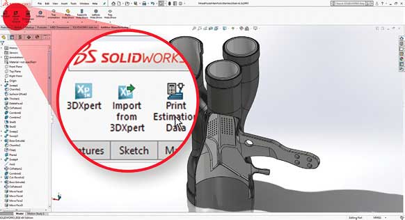
3D Systems’ AM analysis and print preparation software 3DXpert for SolidWorks allows users to bring the modified part back into the CAD program. Image courtesy of 3D Systems.
This is an important step in many lightweighting projects, where lattice structures offer the most efficient way to reduce a part’s weight without compromising its strength.
“The lattice configuration changes based on the orientation on the print tray. It would be very hard to design the lattice without this information,” Barkai says. This information is usually unavailable at the CAD design phase, as it needs to be ascertained and determined through print process analysis.
In mid-February, during 3DEXPERIENCE World, hosted by SolidWorks’ parent company Dassault Systèmes, 3D Systems released an update to its plug-in, 3DXpert for SolidWorks.
With more than 3 million customers worldwide, the SolidWorks CAD user base represents a formidable force. Plugging into this crowd goes a long way to expand the pool of designers with parts destined for production in 3D Systems hardware. This SolidWorks-3DXpert connection, solidified and maintained with application programming interface exchanges and corporate handshakes, symbolize the collective desire in engineering: better bridges between CAD and AM.
More 3D Systems Coverage
Subscribe to our FREE magazine, FREE email newsletters or both!
Latest News
About the Author
Kenneth Wong is Digital Engineering’s resident blogger and senior editor. Email him at [email protected] or share your thoughts on this article at digitaleng.news/facebook.
Follow DE

