

Latest News
April 1, 2012
By Dimitrios Karamanlidis
Editor’s note: For more information on using direct modeling and finite element analysis, please see the author’s step-by-step tutorials using a truss frame structure and thin shell structure as examples.
In the early days of computer-aided engineering (CAE) someone coined the phrase “islands of automation” to collectively describe its various components such as CAD, finite element analysis (FEA), resource planning and the like. Now, islands are not bad per se (think Mykonos!) except there were no bridges connecting them.
Before long someone created a link between CAD and resource planning so that your solid model could be sent from the screen to stereolithography (SLA) — hence, the 3D printer. Likewise, it became possible to upload a computer-generated 3D model of, say, a steel building frame to a computer numerically controlled (CNC) machine and have beams and columns laser cut to size, beveled and coped as desired, bolt holes punched, base and cap plates prepped and so forth.
In contrast to that, CAD and FEA still continued to exist mostly in isolation somewhere out there in the archipelago.
And then somewhere around the early ’90s, SDRC (later to become a part of Siemens) launched the I-DEAS Master Series, in which one could create a solid model, switch to FEA and run the analysis, go back to the modeler and re-design and so forth—all within the same software suite. To be sure, there were some “warts” to be taken care of every time the model was imported into the FEA module, but compared to everything else available, it sure felt like heaven.
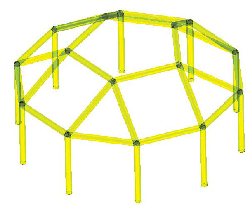 Figure 1: Truss/Frame Structure. |  Figure 2: Truss created in SpaceClaim. | 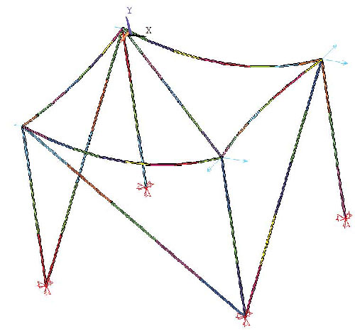 Figure 3: FEA model for truss structure. |
Now fast forward to today’s scenario. Integration between design and analysis has reached the point that a number of robust CAD-FEA combos are available from vendors such as ANSYS, Altair, Autodesk, IronCAD, NEi Software, MSC, PTC, Siemens, Simulia, and SolidWorks to name but a few.
The Combo Platter
When talking about a CAD-FEA combo, two distinctly different flavors can be had. In one case, the link is materialized by way of an application programming interface (API), whereby a click of the mouse from within the CAD software fires up the FEA package. In the second case, the user exports the CAD model to a neutral geometry file (IGES, SAT, etc.) and then imports the same into the FEA software.
No matter how it’s done, keep in mind that moving from CAD to FEA is never as trivial a task as some vendor promotional materials may lead you to believe. For starters, the geometry model used for manufacturing purposes is, for a number of reasons, almost never adequate for FEA.
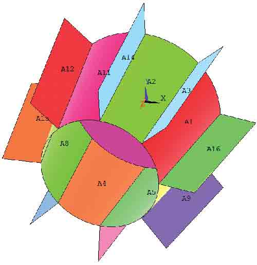
Figure 4: Geometry model for shell structure.
For instance, think of all the bolt holes, welding fillets, bevels, rounds, cutouts, copes, etc. They are important features of the CAD geometry as far as FEA goes, they are in most cases irrelevant and thus must be cleaned away before a sensible stress analysis may be attempted. In the case of a history-based modeler, the cleaning is done by turning off unwanted entities—whereas in the case of a direct modeler, such as SpaceClaim, it is done using the various repair tools provided by the software.
Another reason why a CAD geometry model cannot be used “as is” for FEA: In many cases, the geometry of a model possesses certain symmetries, and it is advisable that when the element mesh is created, these properties are preserved. To accomplish that, it may be necessary that entities in the CAD model (volumes, surfaces or lines) be split into multiple segments. Now what happens if you skip the prepping and proceed to analyze a model cluttered with all kinds of little nooks and crannies? The consequences could range from prolonged runs to totally meaningless results, and everything else in between.
In what follows, the goal is to illustrate how CAD-based FEA is done utilizing the SpaceClaim/ANSYS combo as an example. The basic points made should have validity for any other software configuration, while the specific details would naturally differ from case to case, depending on the available tools.
Truss/Frame Structures
Trusses and frames are integral parts of many product and machine designs, yet when it comes to defining which one is which, it’s not uncommon to encounter confusion. For both, their respective solid models look exactly the same—yet their responses to applied loadings are significantly different.
Let’s start by stating that trusses and frames are simplified models (whether two- or three-dimensional) of “real-world” structures (see Figure 1) whose components are represented by curved or straight line elements. In a truss, the joints connecting the individual members provide for the transfer of forces across elements, but not moments of any kind. By contrast, in a frame, forces as well as moments are typically transferred from an element to its neighbor(s).
In developing a truss/frame model, the underlying assumption is that for each component, its thickness and width are much smaller than the member’s length. The member’s mechanical behavior is modeled quite accurately by a line, making it unnecessary to use two- or even three-dimensional representations, which require more effort to prepare and to solve. Naturally, there are situations where a line representation would not provide for a detailed enough analysis, in which case a surface model or a volume model is the only recourse.
Consider the structure depicted in Figure 2. One starts out by creating a 2D sketch, from which using the Pull tool a 3D solid is obtained. Next we select the four vertical edges along with the four horizontal edges on the top of the solid; activate the Prepare ribbon; select the desired profile; and create the beams. The profile may be either created from the CAD geometry by cutting a cross-section of the respective solid(s), or from the available library of shapes. If the default library shape is not satisfactory, it can be altered with a few clicks of the mouse.
One of SpaceClaim’s strong points is that beams (“children”) remain linked to the original solid (“parent”)—that is, if the geometry of the solid changes, then that of the truss/frame will change as well. To create curved members, the solid is modified using the Bend tool. To create unequally long legs, the top plane of the solid is rotated with respect to one of the edges. Now how about diagonal braces? Because our 3D solid has no diagonal edges, one has to first create the respective center lines, and then place the beams.
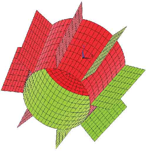
Figure 5: FEA model for shell structure.
Once the model is completed, it is exported to a neutral geometry file such as IGES, which can be read by ANSYS. To successfully complete the export, it is required that not just the beams (their centerlines to be more precise), but also the underlying solid(s) be transferred to the neutral file. In ANSYS, the imported geometry is automatically converted into basic building blocks, according to the hierarchy keypoints, lines, areas and volumes, listed in ascending order. In our case, areas and volumes are not needed and should therefore be deleted.
To check that the model is error-free, invoke the LGLUE and LOVLP commands, which generate new lines by “gluing” input lines and removing duplicate lines, respectively.
To model the structure as a truss, the three-dimensional LINK8 element may be used, for which the only two real constants are the cross-sectional area and the initial strain. Assuming a linear isotropic material, the two material constants to be specified are the modulus of elasticity and the specific weight.
In creating the element mesh, the user has several options to control element sizes. For example, one may specify either the maximum element length or alternatively the number of segments each line is to be subdivided.
Is Direct Modeling At the Tipping Point of Universal Acceptance? To the best of my knowledge, the arrival of SpaceClaim 2007 was first announced in this magazine on March 1, 2007. A few months later, another article appeared that introduced SpaceClaim 2007+ as “a new tool in a mature market that offers a fundamentally different way of working with geometry.” After showcasing some of the features of the new software and contrasting them with those of history-based modelers, the article closed by stating: “If you’re looking at your MCAD system and wondering if there’s something else out there, I can tell you there is. Take a look—we might be seeing the next big thing.” Well, as far as yours truly is concerned, that was like preaching to the choir because I had already made the switch months earlier even after having been an enthusiastic user of a certain history-based modeler since it was launched in 1995. Why? First, it was quite easy to learn the new software. (Full disclosure: At the time, an academic copy of SpaceClaim was made available to me free of charge. Also, I was allowed to call tech support as often as I wanted and ask for help.) Second, coming from the analysis end of things, I knew firsthand that in the case of a model generated by a history-based software, turning features on and off isn’t always as benign as it might sound. Often enough things will blow up because of existing dependencies between retained and turned off features. The SpaceClaim folks did not make things up when they pointed out over and over that no such issues pertained to their software. Did others follow in scores? It depends on your definition of a mass migration. In a recent interview with SpaceClaim’s CEO, he asserted they were selling “thousands and thousands” but not “thousands of thousands” of seats. If SpaceClaim’s “pure direct modeling” (to borrow an expression used by one of its founders in a recent interview) is the best thing since sliced bread, shouldn’t there be a wider proliferation after five years on the market and counting? In a perfect world, governed solely by meritocracy, there should be. But then by the same token, outstanding software such as Cadkey, CADRA, Ashlar’s Vellum, and who knows what else would be widely used members of today’s MCAD scene. So in short, (and to no one’s surprise) I do not have the answer why direct modeling has not taken the CAE world by storm. What I know for sure is that I have a ball using the software and hope to continue that for many years to come. — D. Karamanlidis |
The final step prior to invoking the solver consists of specifying the pertinent boundary conditions along with the external loads (see Figure 3). If the above structure is to be modeled as a frame, it would be necessary to use a 3D beam element such as BEAM4 or BEAM44. In this case, not only are more real constants to be defined than just the cross-sectional area, it is also necessary to specify the beam section’s orientation relative to the 3D space. By default, all joints are assumed to be moment-resistant—thus defining hinged connections is the user’s responsibility.
Plate/shell structures
When analyzing a 3D part or assembly, the use of a plate/shell model is justified in cases where each component is built so that one of its dimensions (thickness) is much smaller than the other two. In the case of a plate, only bending is considered—whereas in a shell membrane action is also accounted for. Figure 4 depicts a simple shell structure that was created in SpaceClaim following the steps listed below:
1. Drew a circular sketch and pulled it to create a cylinder.
2. Added draft to create a cone.
3. Created a thin shell and removed the top face of the cone.
4. Inserted a plane passing through the axis of the solid, and
using that as the sketch plane, drew the profile of the fin.
5. Used the Pull tool on both sides.
6. Used the Move tool to create a pattern of eight solids.
Prepping the created CAD geometry for FEA requires:
1. Extracting the midsurfaces of all solids making sure there
are no gaps in the model.
2. Using the Combine tool to divide the conical surface into eight segments so that the circular symmetry of the model is preserved when the ANSYS mesh generator is invoked.
As in the previous example, when the geometry model is imported into ANSYS the aforementioned precautionary clean-up should be performed to ascertain that no overlapping lines and/or areas exist in the model. For the analysis in ANSYS, we use a flat shell element such as SHELL63—for which thickness (uniform or variable) is its only real constant. The element size may be controlled through the number of subdivisions of each line in the model, resulting in the mesh (see Figure 5).
To summarize, we have illustrated the steps to be taken to perform a CAD-based FEA. The transfer from CAD to FEA was done manually for two main reasons. First, APIs are typically tied to certain versions of the interlinked software, or else they won’t work (e.g., SpaceClaim 2010 and ANSYS 10). Second, and more importantly, in the hands of an untrained analyst, an API may very well become the enabler of a garbage-in-garbage-out exercise.
Dimitrios Karamanlidis, Ph.D., received his education in Germany. His professional career spans more than 30 years as a researcher, teacher and consultant in the general area of CAE. He’s currently a faculty member in the College of Engineering at the University of Rhode Island. He may be contacted via [email protected].
MORE INFO
Subscribe to our FREE magazine, FREE email newsletters or both!
Latest News
About the Author
DE’s editors contribute news and new product announcements to Digital Engineering.
Press releases may be sent to them via [email protected].


