
Connecting input parameters from a system model to drive instant 3D visualization with CAD is not out of the question, as demonstrated here in HBM-nCode’s SystemModeler. Image courtesy of Wolfram Research.


Latest News
July 1, 2015
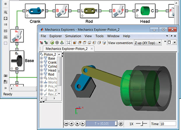 Models you create in Simscape have the same structure as the system you are modeling. In the image above, the parts of the piston are clearly visible in the Simscape model and the 3D animation. Image courtesy of MathWorks
It has been said that England and the United States are two nations separated by a common language. The same might be said of CAD modeling and system modeling. The two disciplines rely on the same vocabulary—model, model-based design, components, input parameters and simulation—to describe different objects and practices from their respective fields.
When CAD modelers talk about “the model,” they’re usually referring to a detailed 3D assembly model, complete with electric components, standard mechanical parts, wire harnesses and manufacturing information. The other side uses the same word to describe a schematic (mostly 2D) representing the data flow, input-output relationship and component hierarchy that depict the inner workings of a vehicle, plane, robot, plant or another complex system. A CAD modeler includes inputs such as wall thickness, extrusion lengths, trim angles and other values that define the geometry of the design. System modelers work with fan speed, valve modulation, temperature and power as inputs. In CAD, simulation means studying how stress, pressure and forces would affect the integrity of the design. System modelers, on the other hand, conduct simulation by computing the effects of varying inputs on the overall structure of the design. The two groups use different software tools. So the work completed in one side won’t be of benefit to the other—or so it seems.
“The tools in the system modeling and simulation industry—not just ours but others as well—have made a big leap in the last five years or so. That hasn’t been well communicated to the CAD community. Most [system modeling] tools are moving in the direction to allow data import from CAD models. In ours, some parts of this are automated so you can get a skeleton structure to start your system model,” says Johan Rhodin, kernel developer at Wolfram.
“The computational fluid dynamics (CFD) model—or a simplified version of it, at any rate—could drive a system model in VisSim [Altair’s software for nonlinear dynamic system modeling],” says Richard Kolk, chief technical specialist for VisSim at Altair. Efforts to bridge the two disciplines will likely continue as multidisciplinary, collaborative product development becomes standard practice and not just a theory.
Where the Two Meet
The general impression is that the detailed 3D CAD model that defines the geometry of a product is not readable in system modeling software; therefore, the mechanical behaviors, geometric values and component shapes already described in CAD have to be redrawn from scratch for the system model in another software program. But, according to the system-modeling experts, the CAD model could be the starting point.
“Mass-spring-damper models are the most basic building blocks for system models. At the simplest level, we can transform a CAD model into a single mass-spring-damper model in VisSim. Then you can refine that model to adequately represent the control system by adding other mass concentration points,” says Kolk.
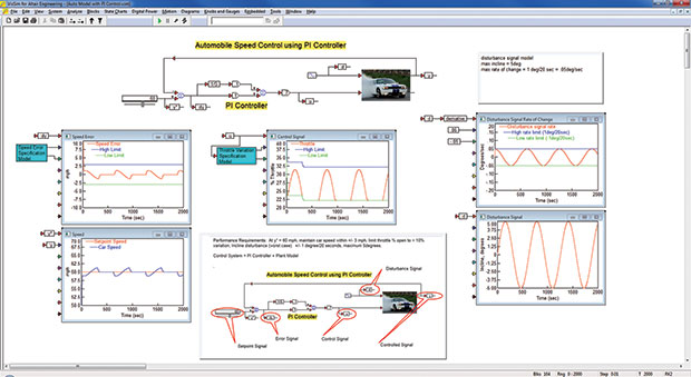 VisSim is used here to model the speed response of a car, with a function of the throttle position and incline angle. The purpose is to design and simulate the performance of a speed controller attempting to maintain car speed at a desired value as the incline angle is dynamically varied. Image courtesy of Altair.
“Any relevant data in the CAD system can be extracted for use in a Simscape model. Often, not all data that is necessary for a Simscape model is present. For example, constraints that define how the parts move with respect to one another are not always defined because the CAD engineer may only be interested in designing the shape of the parts, not in how they move,” says Steve Miller, technical marketing manager for Simscape, MathWorks.
Using system model variables—usually sensor data from tests—as input to CAD to initiate real-time visualization of the simulated operations of a cyber-mechanical system is not out of the question. Describing the features of its software SystemModeler, Wolfram writes that a user can “attach visualization geometries from CAD software to components, and automatically create live 3D animations for models with 3D mechanical components.”
“You can use DIAdem to map the sensors on your prototype to a 3D model and watch the effects of the test playback on the 3D CAD model,” says Stephanie Amrite, product manager for DIAdem, National Instruments (NI).
Sensor Data Gathering and Analysis
Part of the challenge involved in developing an accurate system model is the sensor data collection and analysis involved. Such data, recorded from physical tests, allows engineers to understand the correlations between different system components and how each affects the behavior of the overall system.
NI’s Amrite explained that, in automotive sector, for example, engineers might conduct “component testing, by adjusting the design of a particular component and analyzing the data to see which combinations perform the best under certain circumstances; crash test analysis, by post-processing the large amounts of data collected during a very short crash test; or fatigue analysis, to understand the points at which components or parts break.”
The advantage with DIAdem is the ability to load any file format and perform complex queries to find the data in question. “DIAdem also allows you to pull in individual channels of data, so you can, for instance, review Thermocouple A from File 1, 7, 19 and 34 in a single view without having to open each file, copy and paste the required channel into Excel or another tool,” says Amrite.
For Turbomeca (Safran), a helicopter gas turbine engine manufacturer, conducting altitude tests on a new engine meant “capturing 400 channels of data from temperature, pressure, velocity sensors and accelerometers, generating a total of 5,000 different files,” according to a case study published by HBM-nCode (“Turbomeca Reduces Typical Test Analysis Time for New Engines from 2 Months to 1 Week with nCode Automation”).
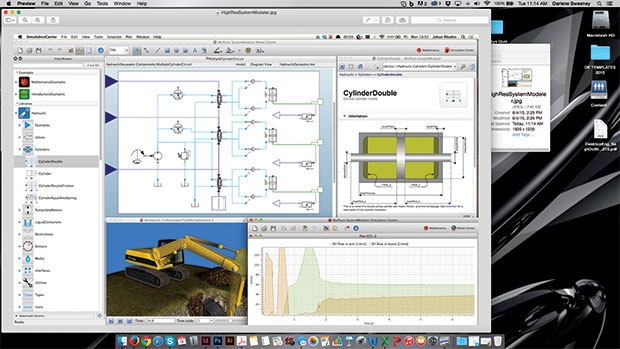 Connecting input parameters from a system model to drive instant 3D visualization with CAD is not out of the question, as demonstrated here in HBM-nCode’s SystemModeler. Image courtesy of Wolfram Research.
Jon Aldred, director of Product Management of HBM-nCode, explained why Excel, usually the go-to tool for managing tabulated data, isn’t ideal for Turbomeca’s purpose. “The data files are ASCII files with over 100,000 rows. Excel does not read this data very quickly,” he said.
Turbomeca currently uses HBM’s nCode GlyphWorks and nCode Automation software to capture, analyze and manage its test data. “The ASCII format was added to GlyphWorks as a directly supported format and so it is much faster to read. In some cases, GlyphWorks was also used to convert it to a binary format, which means subsequent reading of data is even faster,” says Aldred. The case study noted that what used to take 5 minutes to open in Excel now take mere seconds.
With nCode GlyphWorks, Turbomeca cut the typical time required to perform analysis on the data. GlyphWorks took only two-thirds of what it takes to do the same task with VBA (visual basic for applications) scripts. “Most of the analysis is done using standard ‘glyphs’ (analysis building blocks). These glyphs are very efficient computationally and optimized for large data sets. In some cases, Python scripts inside user-defined glyphs are used to replicate specific methods from the VBA,” says Aldred.
No-Coding or Low-Coding
Building a system model is much like building a 3D model with objects from a library of standard components. The drag-and-drop interface and a component library are now regular features in system modeling programs.
“A wide range of capabilities for processing measured data can be handled by expert or occasional users within nCode GlyphWorks’ drag-and-drop interface. The simplicity of its graphical, process-oriented interface ensures engineers spend their time interpreting results, not developing the process,” Aldred says.
“[A VisSim model] is a data flow. You have data sources that produce signals, which are scalar, vector, or matrix. They pass over wires. You build function using VisSim’s basic blocks, such a multiply, divide, and so on. The modeling environment is intuitive. In my experience, someone from a mechanical, chemical, or acoustic engineering background will pick up the language in about two hours,” says Altair’s Kolk.
“You would have components in [SystemModeler], like motors and bearings. You can start building your model by connecting them to other components,” says Wolfram’s Rhodin.
“Constructing a Simscape model is just like drawing an electrical circuit. You pick your components and assemble them in a schematic. To build the model, run the simulation, and review the results, you do not need to write a single line of code. Sure, coding in MATLAB helps automate some routine tasks in Simscape models, such as testing a range of parameter values or analyzing simulation results, but coding is not at all a prerequisite for system simulation,” MathWorks’ Miller says.
NI’s Armite listed the three methods by which DIAdem users can execute data analysis; two of them do not require programming knowledge.
(1) You can use interactive dialog boxes to configure a calculation. The formulas have been programmed with a dialog box acting as an interface to set parameters. DIAdem is preloaded with hundreds of engineering-specific functions, along with a Crash Analysis Toolkit.
(2) You can insert custom equations using a calculator. You can type in formulas to run using the calculator, which does not require any programming. You can also create a series of equations to run in DIAdem based on the outputs of previous calculations.
(3) You can use DIAdem’s scripting editor to create your custom routine. This requires programming, but you can also use the script recorder to get the format of commonly used equations. You can also call existing analysis routines from the scripting environment.
Playing with Numbers
CAD modelers conduct finite element analysis (FEA) to understand how different geometric values affect the performance of a product: For example, what does increasing the wall thickness of an engine housing by 0.2 mm do to its ability to withstand heat? Similarly, once an accurate system model has been developed, engineers could try out different what-if scenarios by altering the sensor input values.
“The ability to do what-if configurations under different operating conditions is one of the primary purposes of model-based design with tools like VisSim,” says Kolk. “VisSim allows you to automate this, so you can slightly alter the parameters and record the behavior matrixes for each [configuration]. You can vary any or all parameters within a range incrementally.”
One of the most complex system modeling exercises Kolk has witnessed is the study of a passenger plane’s anti-skid system. “It involves about 12,000 function blocks, roughly 80 parameters to look at (ranging from simple gain values on signals to priming on logic), across 500 scenarios,” Kolk says.
“Programmatic simulation control is one of the strong points of our software [Wolfram SystemModeler]. You can set up any type of test case or design space exploration. You look at not only different parameters but also different configurations,” says Rhodin.
Rhodin thinks it’s time to address the disconnect between the geometry modelers and system modelers. “For a time, people think it’s enough to do one type of simulation [either with CAD models or with system models]. But actually, there’s value in doing both in concert.” He predicts we may begin to see more “tool couplings.”
Subscribe to our FREE magazine, FREE email newsletters or both!
Latest News
About the Author
Kenneth Wong is Digital Engineering’s resident blogger and senior editor. Email him at [email protected] or share your thoughts on this article at digitaleng.news/facebook.
Follow DERelated Topics


