

Latest News
October 1, 2005
By Cecilia Galvin
College students are known for defying convention, and last year’s University of Missouri-Rolla Formula SAE (FSAE) racing team was no exception.
Although prevailing wisdom in the collegiate Society of Automotive Engineers (SAE) racing competition says that aerodynamic add-ons are not effective at low speeds, the University of Missouri-Rolla (UMR) student team—with its fourth-place finish in 2004—proved otherwise. All it took was hard work, a little luck, and specialized CFD and visualization software.
|
|
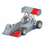
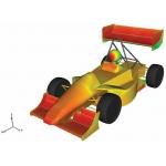
| The model of the car, in Pro/Engineer, has the halves colored to show the split on a symmetric plane. |
When Chris Ford, a transfer student, arrived at UMR in the fall of 2001, he had his sights set on a career as an aerodynamics engineer for a major racing organization. To gain real-world experience, he joined the university’s FSAE team and looked forward to the spring when the team would present its car to the judges and then race the formula-style, open-wheel car against collegiate competitors from around the world.
As the team’s new aerodynamics group leader, Ford quickly pitched his colleagues the idea of using airfoils, or wings, on the car they were designing, building, and testing for the 2002 race.
“The faster you go the more applicable aerodynamics are,” says Ford. “Most people wouldn’t even consider them at speeds below 50 mph. We average maybe 35 or 40 mph, with a top speed of maybe 70 mph. But that’s only for an instant. Our road course has kinks and straights; it’s not an oval track where you maintain a constant speed.”
Still, Ford was undeterred by the conventional wisdom. Using a program called Super Numerical Airfoil Creation Kit, or SNACK, he designed 20 different airfoils that he and his group built from foam models and tested in UMR’s 18- by 18-inch wind tunnel. After determining the downforce each wing produced, the group selected the five best designs and began work with stacked combinations of these.
Wing Strategies
In 2002 the team ran with wings that had only a main plane and a second element on the front, and a main element and a second element on the rear. But that didn’t provide enough downforce, which may have contributed to the team’s 16th-place finish.
|
|
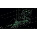
| Gambit was used as a first step to create the block structure, or mesh, around the car. |
For the 2003 racing season, the aerodynamics group experimented with various combinations and decided on three wing elements up front and two in the rear. Unfortunately, the team fared worse overall than in the previous year. Because of the large front wing area, there was more downforce on the front than on the rear. That knowledge informed the aerodynamics decisions for the team’s 2004 season.
“We made the second element in the rear as big as it could be in 2004,” says Ford. “The FSAE rules state that you can have wings that are only so big, so we completely maxed out that envelope.”
With both real-world racing experience and small-scale wind tunnel testing under his belt, Ford, now team captain, wanted to further hone the car’s aerodynamics and increase his team’s chances of turning out a top-finishing car. Ford was running out of time: He was in his senior year, his last for participation in the FSAE program.
Ford devised a two-pronged strategy. He would mesh the solid model of the car, run it in a CFD solver, and then visualize it. He would also try to wrangle some time at a full-scale wind tunnel facility to compare the flow from the visualization software with that from the wind tunnel, and vice versa.
Lessons from the Wind Tunnel
As it turned out, Ford and his team got the car into a wind tunnel before they met the graduate student who would help them run the necessary CFD and visualization software.
|
|
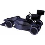
| Meshing the solid model of the car enabled the UMR team to get accurate data about the unique, multi-element front wing. |
After a series of weekly calls to the Jacobs Sverdrup Driveability Test Facility in Allen Park, MI, Ford was able to convince senior aerodynamicist Steve Jacobs to donate eight hours of wind tunnel time. The two arranged for the testing to take place during the university’s spring break, but Jacobs cautioned that he had to approve the team’s test plan beforehand.
“I wrote up a test plan and Jacobs worked on it with me for months to get it perfect,” says Ford. “We tested two wing elements like we had in 2002, then we added a third element. We also tested angles of attack, different height and shape Gurney flaps, sawtooth Gurney flaps, and Gurney flaps on the endplate. We even tested a little bit on cooling ducts to try to get more air into the radiators.”
Although the team ran out of time before they completed the entire test plan, they came home with valuable data as well as video of smoke streamlines from the wind tunnel that they planned to compare with the streamlines in the visualization software.
Computer Data for Comparison
Through a mutual acquaintance, Ford was put in touch with Erich Fitzpatrick, a design engineer and UMR graduate student who had experience with CFD and visualization software.
“I saw the race car and thought, man, this is cool. I would love to help out,” says Fitzpatrick. “So Chris gave me a CD containing IGES and STEP files of the vehicle, and I got started.”
Fitzpatrick imported the files into Pro/Engineer where he cut the car in half, created a mirrored image, then eliminated the bolts and minimized some details while keeping the basic shape of the body, the airfoils, and anything else that would affect the aerodynamics.
|
|
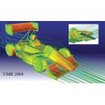
| Streamlines from CEI’s EnSight software matched results of the UMR team’s full-scale wind tunnel tests. Cool colors, like the blue under the front wing in the inset image, indicate low-pressure areas; warm colors indicate high-pressure areas. |
“I drew up individual block sections in Pro/E to ease the meshing,” says Fitzpatrick. “Then I surrounded the spoiler sections so I could do some structured meshing in that area, followed by the wheel and side pods.”
When Fitzpatrick finished the constructive geometry, he imported each block into GAMBIT, Fluent’s CFD preprocessor and meshing package. The idea was to get the most accurate data around the airfoils, and especially around the unique multi-element front wing.
“I used a combination of unstructured and structured meshes,” says Fitzpatrick. “I put the structured mesh around critical areas like the spoilers because structured mesh may provide better solutions.”
When the meshing was complete, Fitzpatrick had a two-million-cell model. He used Fluent’s CFD software running on parallel machines for nearly two days to get results first at 30 mph, then at 70 mph, and then at 100 mph. He also made it possible for the team to modify some of the parameters to see how changes would affect downforce.
Fitzpatrick brought the data into Fluent’s postprocessor to get a cursory look at the forces involved. Then he imported it into CEI’s EnSight to take advantage of more advanced visualization features.
“EnSight gives you more options for visual imaging than a postprocessor,” says Fitzpatrick. “It looks better. The team wanted a good picture for their group presentation on race day, and EnSight enables a multi-window picture. You can get very detailed in layout or representation.”
Worth a Thousand Words
Presentation aside, the aerodynamics group wanted to use EnSight to see the entire flow field with streamlines to get an idea of how the air was responding to the wings. They also wanted to look at pressure plots to see what airflow was working the best and velocity vector plots that show turbulence and flow retardation.
|
|
| CFD results from Fluent are visualized with EnSight. Cool colors represent low pressure; warm colors, high pressure. |
“We concentrated on the pressure contours on the airfoil sections to see what was providing lift and what was providing drag,” says Fitzpatrick. “EnSight enabled us to make recommendations for some changes.”
So how did all of this data jibe with the data from the wind tunnel testing?
“The pounds of downforce from the wind tunnel test and from EnSight were really close. Our goal was to verify the EnSight data with the wind tunnel data and vice versa,” says Ford. “And that’s exactly what happened.”
“Let’s say a couple of years down the road the team is wondering what another new trinket will do on the car,” says Ford. “They don’t have to drive all the way to the wind tunnel in Michigan. They can just draw it on the car, mesh it, and visualize it with EnSight to see what happens.”
Back to the Future
Armed with the 2004 data, UMR’s 2005 FSAE team is well into another racing season. The team is considering a suspension-mounted undertray for the 2006 season instead of a frame-mounted one, which should seal off the undertray and create a vacuum that will help keep the car on the road.
As for Chris Ford, he achieved his dream and now works for Newman/ Haas Racing, a leading Champ Car team.
“I know I wouldn’t be where I am today without Formula SAE,” he says. “This put me head and shoulders ahead of everyone else in marketability. I’m very lucky to have had the experience.”
Cecilia Galvin writes about the CAD/CAM, computer graphics, IT and electronics industries. Send e-mail about this article by clicking here. Please reference “EoA 11/05, CFD and Racing” in your message.
Product Information
EnSight
Computational Engineering International
Apex, NC
GAMBIT
Fluent
Lebanon, NH
Jacobs Sverdrup
Driveability Test Facility
Allen Park, MI
Newman/Haas Racing
Torrance, CA
Pro/Engineer
PTC
Needham, MA
University of Missouri-Rolla
Rolla, MO
Subscribe to our FREE magazine, FREE email newsletters or both!
Latest News
About the Author
DE’s editors contribute news and new product announcements to Digital Engineering.
Press releases may be sent to them via [email protected].


