Closing the CAD to CAE Gap
Can your company improve the design engineering workflow with designer-led analysis?

December 4, 2001
By Pamela J. Waterman
Fifteen years ago or so, mechanical designers began working with improved CAD software and PC hardware to perform basic finite element analysis (FEA). The goal was shortening product development time, but there was valid concern about putting such tools in the hands of non-experts. Garbage in meant garbage out (GIGO), so designs were mostly still “thrown over the wall” to the analysts, then sent back with changes.
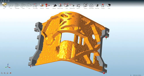 Possible internal structure of an aircraft door hinge, conceptualized and analyzed in solidThinking Inspire software prior to detailed CAD work. Image courtesy of solidThinking. |
The process was inefficient, of course. In some cases, by the time analysts finished months of work, market forces had pushed the designers to make other changes.
Today, both CAD and CAE software offerings include a range of simulation capabilities, and many designers are degreed engineers who do a good job performing stress and yield strength analyses. But the GIGO concept still holds—and because compressing design cycles is more important than ever, software developers are finding ways to bring even more reliable capabilities into the CAD/CAE workflow.
Switching Roles
Just how big is this workflow shift? At the 2012 NX CAE Symposium hosted by Siemens PLM Software, Northrop Grumman’s Dave Fowler gave a presentation on “Structural Analysis Tools Modernization” (available as a PDF download at http://sie.ag/1evU2Pk). Speaking to the growing role of analysis and simulation in the design process, he pointed out that, whereas there used to be six designers for every analyst, the ratio is flipping to 1.2 people doing simulation for every person strictly doing design. This is huge: It means every designer is also doing simulation—and not always with analyst support.
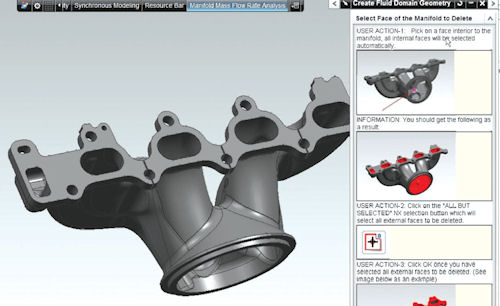 Step-by-step simulation workflow for designer use, built with NX CAE. The interface includes built-in help documentation so the designer is guided to perform the correct tasks: extract the fluid domain in the exhaust manifold, mesh it and then perform a flow analysis. The designer simply picks on various parts of the model, as shown in the documentation pictures. Image courtesy of Siemens PLM Software. |
Such a large role reversal has an equally large ripple effect, as both groups have different skill sets. Ravi Shankar, director of global simulation product marketing at Siemens PLM Software, says this means we have to figure out how to support designers as they take on simulation tasks.
“We must make a toolset such that collaboration between the designer and the analyst is easier,” he says. “One way is with a common platform, with applications that can scale from simple to high-end analysis, such as the NX CAE simulation environment.”
In support of the designer-as-occasional user, NX offers customizable user interfaces (roles), automated scripts (wizards), improved ease-of-use, and solutions data management. For a white paper on this subject, visit http://sie.ag/LNbuUW.
“Simplified analysis was very much the rage, 10 or 15 years ago,” agrees Dale Berry, senior director, Dassault Systemes SIMULIA User Experience. “Software vendors were pushing it, but now companies no longer need to have the value of simulation proven to them. Expert simulation has been and is so successful, our customers are pulling us to bring it across the enterprise.”
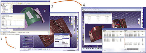 SIMULIA aerospace component example of a workflow for integrating simulation with CAD for composites: designer creates initial layup in CATIA; analyst applies loads and boundary conditions in Abaqus/CAE and runs simulation; then results go back to designer for update in CATIA. Image courtesy of Dassault Systemes. |
The challenge is making simulation an activity not trapped in an expert group, but extending among groups across the company. Berry notes, “You’re not going to give [SIMULIA’s non-linear expert analysis tool] Abaqus to a designer, but he needs access to Abaqus technology to solve things like, when does it break, how long does it last, how much lighter can I make it before it’s going to break?”
Speeding up Aerospace Part Design with solidThinking Inspire Software For a new commercial-aircraft project, you may think a designer—responsible for a single part such as a door—would have difficulty doing meaningful simulations. The challenge is that shapes, aerodynamic loads and boundary conditions at the system level are dynamically changing throughout the (probably years-long) design program. But Altair’s David Mason describes a way of supporting CAE for the designer even on such huge systems. “With solidThinking Inspire,” says Mason, “the designer is creating geometry that has a better likelihood of performing better when it gets to system analysis. Even when the load magnitude changes, the load path doesn’t always change. No one else has such easy-to-use upfront software for CAD designers.” Embraer, Bell Helicopter and Northrop Grummon are all Inspire customers. ” PJW |
To provide such functions, SIMULIA is building these technologies within Dassault Systemes’ 3DEXPERIENCE collaborative platform in such a way that the designer can execute tasks and methods that are pre-determined.
“He might have a menu pull-down that says ‘flexibility,’ depending on the type of tasks he needs to solve and requirements his product has,” Berry offers as an example. “Those methods may be using Abaqus technology, but are predefined by the expert.”
If the designer runs into trouble, the 3DEXPERIENCE platform allows the expert to come in remotely, open up the files, take a look at the analysis as well as the design, and help the designer figure out what’s happening. This approach makes the expert even more valuable—ensuring all the designers in a company are using the method properly.
Berry notes that this subject is very timely: In May, the SIMULIA customer conference will feature a prominent airframe manufacturer speaking on simulation collaboration.
Other Creative Options
Allowing designers access to simulation technology in a way that fits their environment is crucial. In addition, developers must acknowledge the demanding realities of typical job requirements.
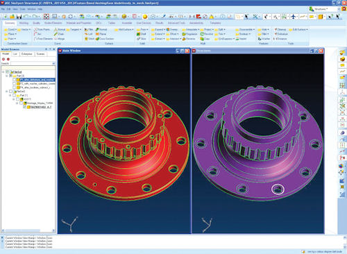 MSC Software’s SimXpert Structures tool, showing the user interface for meshing a gear. Image courtesy of MSC Software. |
For example, besides having CAD skills, designers must understand manufacturing strategies, follow procedures to release parts, and interact with suppliers. As David Mason, VP of Global Automotive at Altair, says, “adding CAE is another barrier. It adds another thing to their plate while shrinking the design cycle, giving them less time and more to do.”
Although automating tasks has helped, he says having the designer do analysis is not necessarily a huge time-saver. To gain that benefit, Altair offers Inspire from its subsidiary company, solidThinking—software that in a way puts simulation before design. More than just a geometry-creation tool, Inspire includes traditional structural simulations for identifying load paths and checking whether a design will support the required load values.
Why So Much Simulation? The Consequences of Failed Prototypes In late 2013, Lifecycle Insights (sponsored by Siemens PLM Software) surveyed 1,005 respondents regarding use of simulation during both concept and detailed product design stages. One topic was the issues that arise when prototypes fail because of poor initial designs. See how much your colleagues agree on the consequences of failure:
Source: The 2013 State of Simulation Driven Design Report ” PJW |
“That’s going to give you a much bigger impact for time reduction, because your analysis is going to confirm that you have good geometry,” explains Jason Napolitano, solidThinking’s executive vice president, global sales. It also leaves more time to optimize the details. In terms of workflow, most designers take the output of Inspire and use it to do detailed design work in their own CAD software. Customers are asking for Inspire to support smooth surfaces, plus more-detailed geometry and simulations. Napolitano says the product’s approach is already a radical change for the industry.
Another way that high-capability analysis companies are supporting designer-simulation efforts is by moving away from pure FEA language. Pierre Thieffry, ANSYS product manager, structural mechanics, observes that advanced analysis tools are easier for designers to understand when the software uses such terms as forces and pressures, rather than “constraints on a node.” This simplification is a key concept behind the ANSYS Workbench environment, supporting the company’s vision of “Simulation Driven Product Development.”
“When a designer sees CAD-integrated tools, they look familiar; the designer can navigate much easier now than 10 years ago,” Thieffry says. With Workbench, he adds, experts can customize the tools and write process guidelines that show exactly what needs to be done on a given type of part. This is right in line with the trends in the aerospace and turbine industry, where he sees CAD designers doing more of the repetitive work on basic parts made of steel, aluminum and titanium, while dedicated analysts handle complex and innovative tasks involving composite materials and coupled physics.
Powerful Templates
Going back at least to 2001, MSC Software has worked to streamline and improve design workflow, starting with embedding complex solver technology in CATIA (now at V5). Offering direct access to Nastran and Adams analysis tools seemed logical, but designers still had difficulty setting up simulations and understanding the results.
“The MSC CATIA solution morphed into a solution for degreed engineers rather than designers,” explains Leslie Bodnar, senior director, global marketing. “Since then, we’ve gone more toward helping customers do [simulation] with CAE templates that help automate certain tasks. That seems to be a better way of moving simulation earlier in the design process.”
Specifically, MSC Software uses templates in its SimXpert product to define a workflow, for several strong reasons listed by Shekhar Kanetkar, MSC Software manager, field support. Consistency is No. 1.
“If you give a problem to 10 engineers,” says Kanetkar, “we joke and say you can get 12 answers. Two will do it two times because they wonder whether they did it the right way (depending on materials and experienced assumptions).”
Other benefits to template use include:
- automation—speeding up such labor-intensive tasks as fuselage or wing analysis
- efficiency—a wizard guides a non-expert through the process
- expertise—capturing the wisdom of experienced CAE users (it’s what Kanetkar calls “engineering acumen”)
Bridging CAD and CAE Experts
Autodesk brings a different perspective to enhancing the CAD/CAE connection, starting with its history of pure CAD rather than analysis. Adding Inventor Professional to its AutoCAD software line gave its customers their first opportunity to do linear stress analyses within their 3D CAD environment. Over the past decade, the company expanded its simulation capabilities with the acquisition of analysis products from Moldflow, Algor and Blue Ridge Numerics, using them to create its Simulation Suite of targeted applications.
“Making simulation available to the masses is a good thing,” says Luke Mihelcic, Autodesk’s cloud marketing manager, noting that the analyst receives a design that needs fewer iterations. “But adding simulation capabilities to CAD tools creates a certain level of responsibility. The challenge is, how does a designer interpret simulation results?”
His company’s response has been establishing a User Experience Group whose tutorials explain what a simulation run means. For example, when values for yield exceed a certain limit for a given material, the tutorial makes the connection of “this means the yield-strength has been exceeded,” and discusses safety factors.
24/7 Analysis
Although the phrase “global economy” may seem both overused and a given, a recurring theme in the CAD/CAE discussion is designer access anytime, anywhere. SIMULIA calls its approach the 3DEXPERIENCE Platform, comprising collaboration, cloud deployment, mobile access and managed access. Autodesk offers a line of cloud-based “360” simulation products, plus mobile apps for general design-direction feedback.
“You can no longer think of design and simulation as completely independent activities,” says Siemens’ Shankar. “What we’re trying to achieve is quality engineering, and that includes both how the product will look and how it will function.”
But as Autodesk’s Mihelcic adds, “Things don’t have to be hard to be accurate.”
Contributing Editor Pamela Waterman, DE’s simulation expert, is an electrical engineer and freelance technical writer based in Arizona. You can send her e-mail to [email protected].
More Info
Subscribe to our FREE magazine, FREE email newsletters or both!
About the Author
Pamela Waterman worked as Digital Engineering’s contributing editor for two decades. Contact her via .(JavaScript must be enabled to view this email address).
Follow DE

