Designing with AM in Mind
Designers and fabricators must support one another to avoid print failure.
AM system maker Desktop Metal developed a software called LiveParts, which uses algorithms to generate topology by adding up virtual cells (as opposed to removing materials). The approach is known to produce shapes much more suitable for AM. Image courtesy of Desktop Metal.
Post-Processing and Finishing News
Post-Processing and Finishing Resources

Autodesk
Dassault Systemes
Latest News
November 1, 2019
Classic parametric CAD design is a reflection of the subtractive manufacturing methods it was meant to address. The way you use the software’s various commands to remove materials from a primitive shape—a 2D profile with a certain depth or height—to create the final part’s geometry, mimics the way the part will eventually be produced in a machine shop.
But additive manufacturing (AM), or 3D printing, is the opposite of subtractive manufacturing. The technology creates the part by building the geometric volume one layer at a time, by depositing and bonding the materials inside the build chamber. AM-specific design software programs are emerging, and the number is increasing. For example, AM systems maker Desktop Metal has developed its own design software, dubbed Live Parts, which uses algorithms (so to speak) to grow a part by adding volumetric particles.
But software like Live Parts is an exception. Currently, CAD software remains the dominant design tool. For this article, we asked AM experts for guidance on the counterintuitive yet unavoidable workflow: How to design for the additive process in the CAD tools that mimic subtractive methods. Most of them shared a similar reply: You need a different mindset.
Working Closely with Fabricators
Ray Huff, associate engineer, Wohlers Associates, is one of the instructors for the recurring design for additive manufacturing (DfAM) seminars organized by Wohlers Associates, an analyst firm known for its annual AM industry reports.
“A lot of times, the designers are distanced from the machine operators. The designers design, then send the file to fabrication shops or manufacturing teams to get the part made,” says Huff. “With AM, because the design is so closely tied to the process, it’s really helpful for the designer to be in frequent contact with the machine operator. The machine operator can often tell you why your part might fail, or where you need more support in your part.”
Design for Distortion
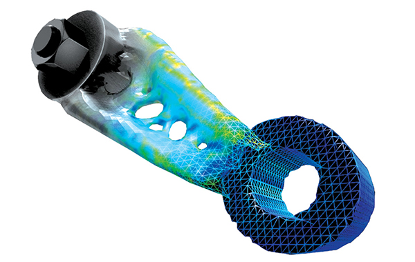
One thing the AM machine operator might tell you is how to design for distortion. The thermochemical process involved in many AM systems—especially in metal AM systems—leads to certain part distortions. That means, to get the desired geometry, you need to predict the distortion that will take place in the build process, then create a slightly exaggerated geometry that will result in the desired shape after distortion.
Simulation software maker ANSYS offers AM-centric solutions, dubbed ANSYS Additive Suite, ANSYS Print and ANSYS Prep. The software includes tools to address distortion compensation. Those working in CAD software may also use integrated simulation programs to simulate and predict the distortion. For example, designing the geometry in CATIA (part of Dassault Systèmes’ 3DEXPERIENCE brand) and simulating the thermal activities in AM in SIMULIA (also from Dassault Systèmes).
Overhangs and Lattices
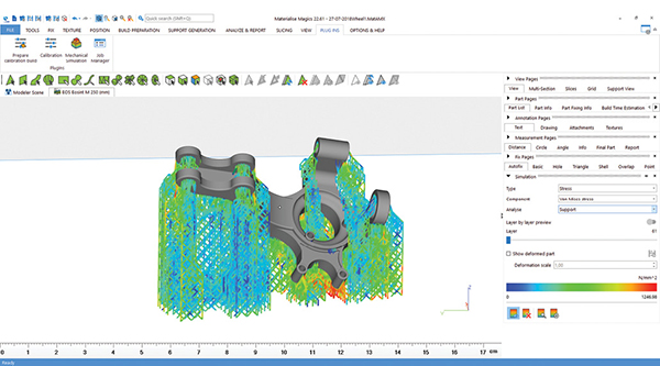
Materialise is known for its Magics STL-editor software, for preparing geometry destined for AM. Catering primarily to the manufacturing and medical sectors, the company also offers printing services.
“The main reason that parts fail is that the design was never optimized for 3D printing,” says Dries Vandecruys, design engineering manager, Materialise. “Something designed for traditional manufacturing with overhangs and without gradual wall thickness, increases the chance of failure tremendously. So first of all, take the specificities of metal 3D printing into consideration when you’re designing your parts.”
“Materialise e-Stage software for metal really helps to tackle these problems,” adds Vandecruys. “It can generate the support structures automatically within Magics. With the simulation module you can go even further and immediately simulate the print process so you can change your design if needed. This all helps to reduce the number of build crashes significantly.” (For more on the subject of overhangs, read “AM Simulation Gets More Complex with Metal.”)
Autodesk offers Autodesk Netfabb, a connected design and simulation package for AM. It also offers Autodesk Fusion 360, an integrated CAD-CAM-CAE package with cloud-augmented features. Fusion 360 includes generative design, which lets the software automatically generate suitable topology based on user-specified parameters (such as stress loads, materials, mass and weight).
“Today’s generative outcomes are all solid CAD geometries based on singular materials. They may avoid creating features like large overhangs to minimize the need for support structures in AM and control the minimum member size so that they can be printed, but they are not aware of the parameters with which the object should be printed. They assume the design will be fully dense and homogenous in its response to external loads,” notes Sualp Ozel, senior product manager, Autodesk.
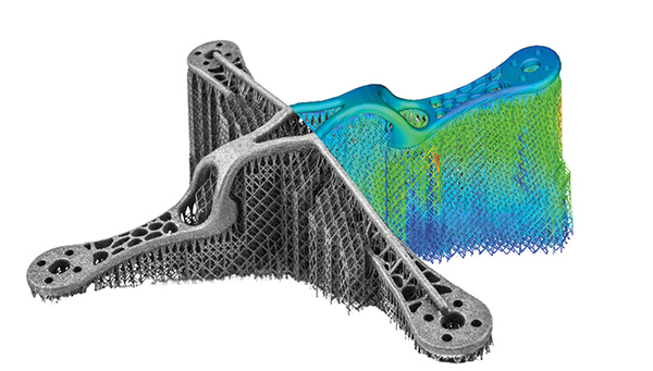
With AM, there’s also an option to design a part with lattice structures, resulting in lighter parts. It’s an option that’s usually too costly or impractical to produce with traditional manufacturing means. Some newer AM-focused software, such as nTopology and Frustum (acquired by PTC last November), include this feature. Established CAD and simulation software developers are also adding the feature to take advantage of AM’s unique strength.
Simulating the Build Process
In standard CAD design, you simulate how the part responds to stress loads, such as pressure, weight, heat or airflow. With AM, simulating the build process is also part of preparation. Without this step, the risk of a failed print job increases.
“Make sure to validate [the part] virtually through a simulation package before you start printing. With our simulation module in Magics, we made simulating easy as you can simulate the build process within the print preparation software without having to open new programs,” says Vandecruys.
“With metal AM you really need to design the build, not just a part. Think about how this will be manufactured: Will you print many of the same parts on one build plate or build several different parts at a time to be assembled later? Once this is known, you should have an idea of the orientation it is best to build each part in, and therefore allow you to design for the process better,” says Mark Rushton, product portfolio manager, Dassault Systèmes.
Orientation can potentially speed up the print process. A single print tray or print chamber can simultaneously produce several parts. Thus, being able to fit as many parts or units on the tray affects production output.
But this is also offset by the fact that, in certain orientations, the part may require more support structures to prop it up during the print process. Finding the best orientation strategy and ways to mitigate the need for support are new skills CAD designers are gradually learning as they dip their toes in AM.
Don’t Forget Post-Processing
Huff calls post-processing AM’s “dirty little secret.” Vandecruys warns “post-processing is quite labor intensive. This limits your design freedom and requires some extra thought in the design phase.”
Post-processing occurs after the part comes out of the printer. It may involve removing materials trapped inside the canals, pockets and chambers; smoothing the contact surfaces to remove print artifacts; and removing the support structures that are required for the print process but are not part of the original design.
If the printed part were a prototype or a one-of-a-kind part, the issue may be irrelevant as it can be dealt with as a one-time measure. But the amount of work is significant for those considering AM or metal AM as a means of mass production.
“Even if you have designed it well and produced it in AM, there may still be surfaces that need to be machined, or internal channels that need to be cleaned out,” Huff points out. Some of these issues may be mitigated in the design phase by avoiding the type of geometry that results in post-processing.
“When you print big meshes, like porous structures for the medical industry, it’s really important to think about the cleaning process upfront and how you will assure that you get all the powder out of the mesh,” says Vandecruys.
More than traditional CAD design, designing for AM means understanding how the part will be built. This knowledge resides largely in the manufacturing domain, not conceptual design. Therefore, to avoid potentially costly metal print job disasters, designers need to collaborate closely with manufacturers.
More Ansys Coverage
More Autodesk Coverage
More Dassault Systemes Coverage

Subscribe to our FREE magazine, FREE email newsletters or both!
Latest News
About the Author
Kenneth Wong is Digital Engineering’s resident blogger and senior editor. Email him at [email protected] or share your thoughts on this article at digitaleng.news/facebook.
Follow DE

