Developing Turbochargers with CFD


December 9, 2014
 Dear Desktop Engineering Reader:
For most people, turbochargers are a thing that racecars and hot-rodding teenagers have. Reality is more expansive. These days, more and more autos, light-duty trucks and gas-electric hybrid vehicles come with some sort of turbocharge mechanism to boost the power of their small, fuel-efficient engines. Take the Prius, for example. It has a “power” mode that provides some giddyup-and-go to help climb steep slopes or cut off somebody barreling down the lane as you merge onto a highway.
 For engineers, a turbocharger means multiple physics challenges like structural and CFD (computational fluid dynamics) analyses. It means design considerations such as determining the most efficient volute and blades for maximum power efficiency. It means ensuring the turbocharger’s structural integrity and testing the entire, complex operating condition envelope. You’re concerned about noise, emissions, component size and operational life. Complex stuff. Today’s Check it Out link takes you to the “Developing High Performance, Reliable Turbochargers with Computational Fluid Dynamics” landing page where you can explore the solutions ANSYS offers for turbocharger design and analysis.
ANSYS has a set of 1D, 2D and 3D tools that integrate through the ANSYS Workbench framework and with its Turbo System. This creates a unified environment for the multiphysics simulation approach turbocharger design and analysis requires. Among the notable capabilities that ANSYS provides is a 2D through-flow solver that lets you run some quick initial analyses of your rotating machinery. What this means for you during the course of a project is that you’ve filtered out non-viable design alternatives early on, enabling you to carry out more in-depth and detailed 3D analysis on a smaller, more viable set of candidates as you progress. Additional technologies to draw upon include a tool for rapidly designing 3D rotating machinery components, the ability to run hundreds of design and operating condition simulations automatically as well as design optimization capabilities through ANSYS DesignXplorer.
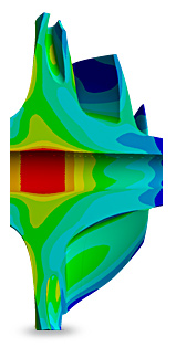
This landing page has two main sections. In the middle of it you’ll see a brief video, which is followed by three example screenshots from it. These screenshots depict static pressure in a compressor, flow conditions at the operating point between choke and surge and then the area of maximum stress in the bore.
The registration-free, 6-plus-minute video provides a step-by-step demonstration of how you can use ANSYS’ CFD, mechanical and other technologies to predict turbocharger performance and ensure structural integrity. Specifically, the video looks at developing efficient and high-performance flow paths. The latter, incidentally, really means that the video and the technology it portrays have applicability across a variety of turbo-machinery simulations, such as fans, pumps, turbines and torque converters, in industries as diverse as aerospace and HVAC (heating, ventilation and air conditioning). The video is a music-scored, captioned presentation almost exclusively of screenshots, so switch into full-screen mode to better read the captions and see what’s going on in individual screens, especially the setup displays.
You can access the second main component via a clickable tile at the top right of the landing page. This will take you to an on-demand webinar called “Improving Turbocharger Design” (registration required). Essentially, this 54-minute webinar covers the same material as the video, but in far greater detail.
Here, you get a demonstration of the mechanical and CFD simulation workflow to verify the structural integrity and the aerodynamic system design of a full turbocharger assembly. You begin at the earliest stages of the workflow and proceed on through CFD post-processing. You get a detailed discussion of blade design, impellor meshing, volute design and meshing and so on.
In the webinar, you are also introduced to two new ANSYS features. The first is ANSYS Vista TF for preliminary design optimization. It’s integrated into ANSYS Workbench. The second is an exit-corrected boundary condition for turbomachinery performance mapping in ANSYS CFX. The webinar, which was first broadcast in mid-October, wraps with two case studies of the ANSYS tools in action.
All in all, this is a fascinating presentation. If turbochargers are a component of your work, the “Developing High Performance, Reliable Turbochargers with Computational Fluid Dynamics” landing page is a resource that gets a must check out grade. If other types of rotating machinery are more your gig, this landing page is still well worth your time because pretty much everything you’ll see is adaptable to your work. Hit today’s Check it Out link and see for yourself.
Thanks, Pal. – Lockwood
Anthony J. Lockwood
Editor at Large, Desktop Engineering
Subscribe to our FREE magazine, FREE email newsletters or both!
About the Author
Anthony J. Lockwood is Digital Engineering’s founding editor. He is now retired. Contact him via [email protected].
Follow DE

