Defeaturing CAD Models: Different Strokes for Different Folks
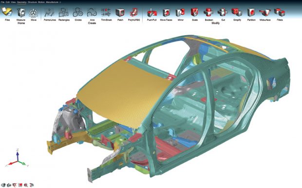
Defeaturing tools should look and feel differently for the conceptual phase (Altair solidThinking Inspire Concept Level, top) and the detailed phase (Altair HyperMesh Detailed Level, bottom), because the users’ goals are different. Images courtesy of Altair.
Pre-processing and Meshing News
Pre-processing and Meshing Resources
January 2, 2018
Defeaturing—removing rounded edges, small holes and other nonessential details from the 3D CAD model—is one of the necessary evils of simulation. It proved so tedious to defeature in parametric CAD programs that newcomer SpaceClaim was able to capitalize by positioning itself as a better defeaturing tool. Subsequently, SpaceClaim was acquired by simulation software maker ANSYS in 2014.
The benefits of defeaturing manifest as faster simulation runs and fewer computing cycles. The more complex the model, the longer it takes to simulate. Conversely, the simpler the model is, the faster it is to solve. In product development, time and computing are both cost items in the budget.
“It’s expensive to run analysis on big supercomputing systems. So by removing some fillets or fasteners, your analysis gets to the conclusion much faster,” says Todd Reade, CEO of TransMagic. “We’re in the process of developing a defeaturing tool right now; the goal is to speed up the analysis process.”
 Aimed at the conceptual design phase, ANSYS Discovery Live offers users a way to quickly simulate and validate complex design ideas. Image courtesy of ANSYS.
Ironically, defeaturing also adds some complexity to the pre-processing workload. “The upfront cost of defeaturing a part needs to be weighed against the fact that removing features may result in further downstream issues. For example, removing a fillet may introduce a stress concentration, which may drive the design,” cautions Stuart Sampson, VP, HyperWorks Enterprise Implementations, Altair.
Not Rocket Science, but Rocket Scientists May Use it
Borrowing some words from the Founding Fathers of the U.S., TransMagic proclaims on its home page: “We the people of TransMagic, Inc., in order to form a more perfect design world, establish best practices in 3D CAD reuse, ensure high fidelity models, provide easy to use solutions ...” Best known for its CAD translation and healing products, TransMagic now embarks on developing a defeaturing program.
“Our plan is to let the users select a feature, then tell the software, through a guided wizard, whether they want to remove all features of the same type of a certain size,” says Reade. “So if you have hundreds of nuts and bolts in your assembly model, and you don’t want to include them in your analysis, the software will remove them for you in one step. You’ll be able to do it through the assembly hierarchy tree, or by selecting the feature directly on the model.”
This method is fairly consistent with the defeaturing tools found in many CAD and analysis programs. It lets you set a threshold (for example, holes with diameters smaller than X), then automatically remove the targeted features in a single sweep.
“You don’t have to be a rocket scientist to use our tools, but many rocket scientists do use them,” quips Reade. “What we’ve seen is, people don’t like to have to learn another software, whether they’re technical or not. We want to keep the UI (user interface) simple so they don’t have to spend hours in training courses,” Reade adds.
The company’s upcoming defeaturing product interface is also designed for geometry simplification for internet protocol protection. The product will be a pre-processor to FEA (finite element analysis) and CFD (computational fluid dynamics) applications.
TransMagic licenses modeling technologies from many leading CAD vendors to be able to read and edit common CAD file formats. “Our expertise is in the way we integrate all of these, so you can move data from mesh models to faceted models to true CAD format,” says Reade.
According to Reade, the upcoming defeaturing product will likely be offered as an add-on to the company’s existing products. It may also be part of TransMagic Expert, a CAD data exchange product in the company’s portfolio.
Apples and Oranges
John Graham, product marketing manager for ANSYS, points out that a designer’s defeaturing needs and an expert’s defeaturing needs are quite different, as a consequence of the difference in their skills and goals. Therefore, the software tools they use should look and operate differently.
Last September, ANSYS launched ANSYS Discovery Live, described as “instantaneous simulation, tightly coupled with direct geometry modeling, to enable interactive design exploration and rapid product innovation.” Discovery Live is not meant for the detailed design validation phase, where every decision carries a certain risk and safety implications. The software is intended for the conceptual design phase, where designers are exploring ideas and seeking general confirmation of their viability.
“With ANSYS Discovery Live, we’re not replicating the tools we offer to the analysts,” says Graham. “The goal is upfront simulation, to find the right design direction, to find insights. Designers with those goals don’t need to be as concerned with details like holes, rounded edges and bolts. So they can remove them without affecting the quality of the design.”
Such small details do make a difference in the design validation phase, usually involving experts and analysts. Different from the conceptual phase, removing or keeping certain small features in this stage is no longer a risk-free or low-risk decision.
With SpaceClaim as the geometry engine behind it, Discovery Live allows automated discovery and removal of a class of features (such as blends and holes). “That approach works with simple geometry,” says Graham. “But if your geometry is more complicated, or if you want more control over the decisions, you have that option as well. The new solver technology allows for as much complexity as you want without an increase in solve time. Complexity is free when doing an upfront analysis in ANSYS Discovery Live.”
Conceptual and Detailed Views
The key is to automate the tedious manual defeaturing process, according to Altair’s Sampson. “Assuming there are several design iterations as the part matures, there’s also a real cost involved in having to defeature multiple iterations of the same part,” he points out.
Altair is known for OptiStruct, a structural analysis solver for linear and nonlinear problems under static and dynamic loadings. The solver is the underlying technology in its HyperWorks simulation suite. Under its solidThinking brand, the company also offers designer-friendly simulation, topology optimization and geometry editing packages.
“Batch-meshing and mid-surfacing within HyperMesh support the automatic recognition of geometries like holes, logos, fillets and flanges and can treat them accordingly,” says Sampson. “Within solidThinking Inspire, there are many defeaturing capabilities, which can automatically detect and remove features if required.”
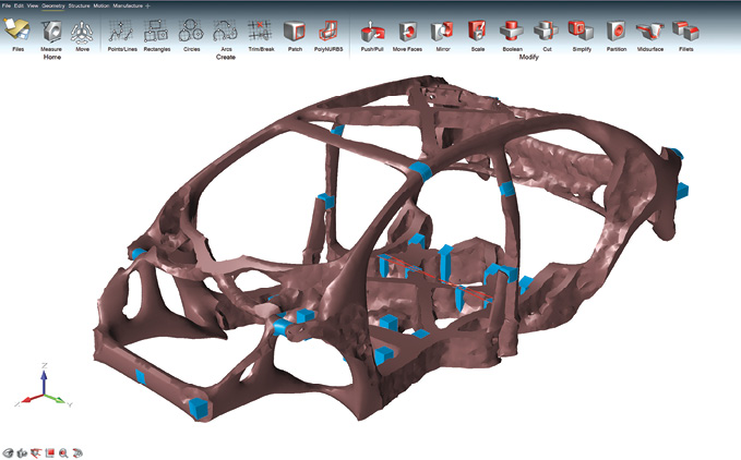
 Defeaturing tools should look and feel differently for the conceptual phase (Altair solidThinking Inspire Concept Level, top) and the detailed phase (Altair HyperMesh Detailed Level, bottom), because the users’ goals are different. Images courtesy of Altair.
Sampson, too, makes a clear distinction between how designers in the conceptual phase view defeaturing and how an analyst might view it in the detailed phase. “The concept level is really focused on generating a design concept and would include basic design simulation and optimization. In addition, a manufacturing feasibility assessment may be conducted. The outcome is a conceptual design decision. solidThinking Inspire targets this exact use case,” he says.
For the detailed design phase, HyperMesh, SimLab and HyperCrash are better options, according to Sampson. “The detailed level (high-end simulation) targets full system level simulation. Detailed simulation and optimization studies would be performed covering a number of different design variants. In-depth manufacturing simulations studies would also be performed.”
Skip it Altogether
Deciding what to keep and what to delete is not always straightforward. Some of the small details you choose to exclude may turn out to be critical features that affect the part’s longevity or durability in actual operation. So if you design based on simulation runs performed without them, your design would be doomed to fail. Why take the risk? Why not use the 3D CAD geometry as is? Assuming there’s no computing penalty to pay, this would seem to be an ideal approach.
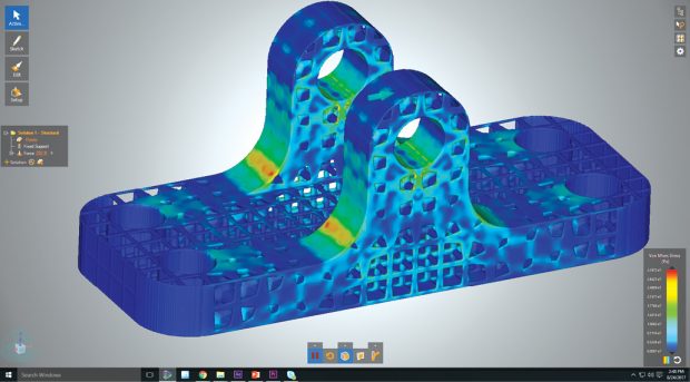
And it’s the approach proposed by Ken Welch, cofounder and CEO of SIMSOLID Corporation. “Use the model that represents how you intend to manufacture it,” he says. “Tiny holes, blended corners—you can leave them in.” SIMSOLID solves models at the assembly level, not just at the part level, which also distinguishes its technology from many other solvers that can only handle part-level simulation.
“With SIMSOLID, you don’t pay a computing penalty if you don’t defeature your model,” says Welch. “It’ll still solve the model in seconds to minutes even if you use a model with full details. Most FEA solvers use older techniques. Our technique solves fewer equations, but the equations are more pertinent to your model.”
Explaining its technology, the company writes: “SIMSOLID does not use the point-wise degrees of freedom (DOF) inherent in traditional FEA. SIMSOLID DOF are functionals with geometrical support in the form of volumes, areas, line clouds and point clouds. This provides the ability to handle geometrical imperfections, as well as assembly contact imperfections like gaps, penetrations and ragged contact areas … [The approach allows] very large and/or complex assemblies to be solved quickly on desktop-class PCs.”
Altair’s Sampson thinks defeaturing may soon become a moot point in simulation. “It’s probably less important now than it was a few years back,” he says. “Traditionally, defeaturing was necessary to ensure good mesh quality, reduce the meshing time and in some cases, reduce the simulation time. With an established trend of reducing global mesh sizes, the feature adherence of the mesh to the original geometry is now becoming an easier task.”
More Info
Subscribe to our FREE magazine, FREE email newsletters or both!
About the Author
Kenneth Wong is Digital Engineering’s resident blogger and senior editor. Email him at [email protected] or share your thoughts on this article at digitaleng.news/facebook.
Follow DE

