Editor’s Pick: Optimize Multiple Circuit Elements in Electromagnetic Space
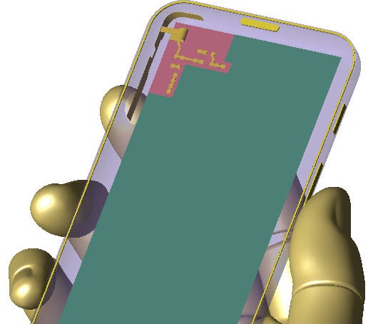
Remcom says that its new Circuit Element Optimizer is able to recognize and consider multiple modes of operation such as a mobile phone in free space versus one held in a hand when selecting component values. Image courtesy of Remcom Inc.
Electromagnetic Simulation News
Electromagnetic Simulation Resources


Latest News
June 3, 2015
 Dear Desktop Engineering Reader:
 Remember when a new model of a popular smartphone came out and immediately users complained about its bad reception? The company said your hand caused attenuation of the phone’s antenna performance. Your solution? Change your grip or buy a bumper case. Such tone deafness is how you earn a hurricane’s worth of blowback from users. While interference is a fact of life, you can design a lot of it out. Today’s Pick of the Week might have helped this company place its phone’s antenna in a better position.
Remcom has a new Circuit Element Optimizer add-on module for its XFdtd electromagnetic (EM) simulation solution. They engineered the module to help antenna designers and RF (radio frequency) specialists select the optimal component values for a matching network layout, printed circuit board (PCB), antenna, filter and other RF structures.
Perhaps the neatest characteristic of this module is that circuit elements remain in the EM layout structure during optimization. This should smooth antenna-matching workflows since you don’t have to simplify matching circuits separately from your EM simulation. By enabling you to optimize in EM space, the Circuit Element Optimizer also gives you the ability to tackle problems involving multiple antennas that both serve several bands and interact with each other as well as the mobile device, all of which can affect antenna match simultaneously.
The Circuit Element Optimizer characterizes RF structures using full-wave FDTD (finite difference time domain) simulations. This ability lets you account for different EM phenomena that affect the RF structure and components, such as the coupling between the driven antenna and nearby copper traces.
Circuit Element Optimizer supports the newest components like fixed and ideal resistors, inductors with user-defined equivalent series resistance and passive tunable integrated circuits. It also supports different physical configurations. That means you can realize the trade-offs in efficiency between different usage scenarios.
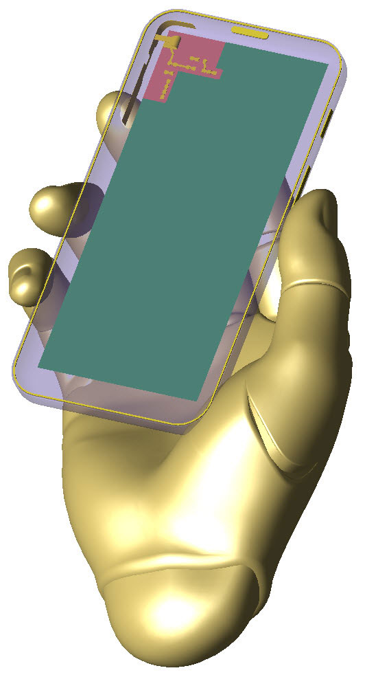 Remcom says that its new Circuit Element Optimizer is able to recognize and consider multiple modes of operation such as a mobile phone in free space versus one held in a hand when selecting component values. Image courtesy of Remcom Inc.
You can learn more about the Circuit Element Optimizer add-on module for Remcom’s XFdtd EM simulation software from today’s Pick of the Week write-up. Hit the first link at the end of the write-up to access the module’s webpage. At the bottom of that page, you’ll find a link to a white paper with a technical explanation of how XFdtd equipped with the Circuit Element Optimizer operates. There’s also an interesting application example titled “Matching Network Design for GPS/Bluetooth Antenna.” Both are registration free. Good stuff.
Thanks, Pal. – Lockwood
Anthony J. Lockwood
Editor at Large, Desktop Engineering
Subscribe to our FREE magazine, FREE email newsletters or both!
Latest News
About the Author
Anthony J. Lockwood is Digital Engineering’s founding editor. He is now retired. Contact him via [email protected].
Follow DE

