

September 1, 2014
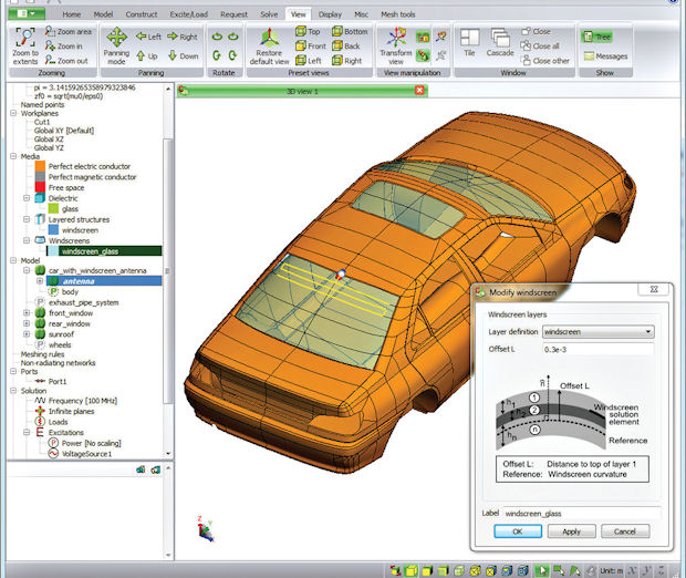 Windscreen antenna definition as part of CAD model creation, for analysis with Altair/EMSS FEKO software. Image courtesy of Altair/EMSS.
Collision-avoidance systems, deep-tissue heating devices and induction-heating stovetops all owe their existence to designs that used to be mostly mechanical, yet now include complex electromagnetic (EM) components. When working with low frequencies (as in motors, loudspeakers and transformers) or high (for antennas, microwave ovens and particle accelerators), mechanical engineers must move beyond electronic circuits and control systems into the realm of EM field theory. This step means adding new considerations to design and analysis tasks.
Knowing which aspects of an EM model are critical or minor for input to a mechanical analysis can be tricky. The finite element analysis (FEA) meshes for each physics simulation are most likely not the same—for example, you must model the air as a propagation path. Time-scales for electric, thermal and mechanical simulations can differ by a factor of 100. And combining EM and mechanical analyses requires twice the decisions about importing geometry, setting boundary conditions and defining material properties.
New Design Strategies Needed
Considering the challenges of EM simulations, Walter Frei, a COMSOL Multiphysics electrical engineer says, “A good structural or thermal analyst can usually have an intuitive feel for what the solution will look like, even before they do much analysis. However, electromagnetics problems can be a lot harder to predict prior to analysis, especially if you consider induced currents, magnetic fields and resonant phenomena.” His advice to mechanical engineers tackling their first EM projects: “Be familiar with all aspects of the design—the material properties, the operating conditions and most importantly, the outputs.”
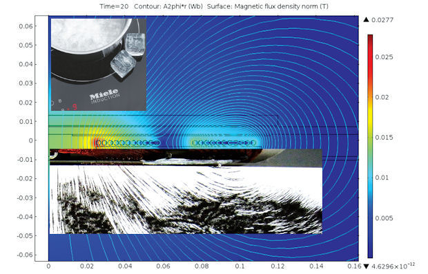 A Miele induction-heating stovetop (right) delivers energy directly to the pot as well as the food within—eliminating the need to heat the stove surface as an intermediary step. Comparison of measured and simulated magnetic flux density, with excellent agreement, as analyzed with COMSOL Multiphysics software. Image courtesy of COMSOL.
Standard steps apply, whether evaluating mechanical or EM part behavior. As with any simulation setup, says Pierre Thieffry, ANSYS product line manager for structural mechanics, engineers must define the loads, boundary conditions and forces at work.
“You must understand which data will have an influence on the model,” he continues. “A potential source is heat transfer: If you look at EM systems, they usually induce losses. This means temperature changes in the body, which creates stresses due to thermal deformations (temperature differences in the structure). This effect could also be time- and frequency-dependent.”
Designers need tools to readily transfer this data from one simulation to the other—sometimes in both directions.
“ANSYS Workbench is ideal to do that,” says Thieffry. “Users just have to take the results of the electromagnetic simulation and drag-and-drop them on the project page to link them to the setup of the other simulation.”
The Workbench I/O function takes care of data mapping and formatting, he adds, even if the mesh doesn’t match up between the EM and structural simulations, which is usually the case. With ANSYS Workbench, users can couple ANSYS Maxwell models to ANSYS Mechanical, ANSYS Fluent or ANSYS Icepak to perform a stress, computational fluid dynamics (CFD) or thermal analysis.
The operational frequency of EM components and systems may encompass the kilohertz, radio frequency (RF), microwave or even optical ranges, with each band requiring different mathematical approaches to simulation for the most accurate results. At Computer Simulation Technology AG (CST), this requirement is managed by the company’s “Complete Technology” approach across CST STUDIO SUITE software.
“This means all our different solvers, optimizers and post-processing options are available within the same user interface, and can use the same models,” says CST Technical Writer Stephen Murray. “For example, for an EM simulation, a particle simulation and a thermal simulation, you can use the same model—and the results from one can be imported directly into another.”
 Magnetic flux density in a linear motor, calculated with ElectroMagneticWorks EMS analysis software (available as an add-on to SolidWorks and Autodesk Inventor). Image courtesy of ElectroMagneticWorks.
Since 2012, CST STUDIO SUITE has supported linking multiple simulation and post-processing tasks with its System Assembly and Modeling (SAM) framework. This tool breaks down and automates workflows as a series of tasks. It chains together multiple multiphysics (MP) simulations, even with different solver types—a parabolic dish and a feedhorn, for example. It uses the same model and parameters, then optimizes the results. The 2014 release offers a wizard that helps users create full-wave EM simulations combined with thermal simulations. Mechanical simulations can be added to calculate part expansion and detuning effects.
EM is just one of the many realms addressed by COMSOL Multiphysics software, which allows users to work in an integrated environment. Users define the geometry, set up the physics, create the mesh, find solutions and optimize results—all in one graphic user interface. Different modules target RF/Microwave, AC/DC, plasma or particle tracing; applications include bundled transmission cables, RF filters for a cell-phone base station, or the latest in home appliances.
Breaking Down the Problem
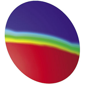 This satellite reflector dish shows a solar heating pattern when the dish is partially shadowed. The calculation was performed with the thermal stationary solver in CST MPHYSICS STUDIO. Images courtesy of CST.
Making it simpler to import CAD data, create meshes and select solvers can ease the transition between EM and mechanical analyses. FEKO software from EM Software & Systems (EMSS, recently purchased by Altair) pays close attention to exactly these tasks and more, with applications including the design and placement of antennas, RF components, radomes and bioelectromagnetics. Three particularly relevant modules and their functions are CADFEKO (CAD import), POSTFEKO (post-processing) and EDITFEKO (scripting).
Explains Ulrich Jakobus, the original author of FEKO software, as well as the EMSS director and FEKO product manager, “We try to make the CAD import process as streamlined as possible by carefully selecting a number of default settings of certain parameters that should work reasonably fine in most cases. For specific requirements, advanced users can have more control over these parameters.”
Default and advanced settings are available in CADFEKO for fixing and healing CAD files. For really challenging cases,
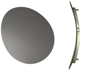 Calculated deformation of a satellite antenna reflector caused by uneven thermal expansion (exaggerated plot), performed with the structural mechanics solver in CST MPHYSICS STUDIO.
CADFEKO interfaces with more powerful pre-processing tools like Altair HyperMesh. To take advantage of parallel processing, FEKO’s solvers have been rigorously parallelized for both distributed and shared memory architectures.
“We observe excellent scaling of both memory and run-time,” says Jakobus. “GPU computing is also supported for specific solvers, and will be extended in the future to other algorithms as well.”
Another business move that tightened the connection between a specialized EM design tool and a general analysis package came in 2011: CD-adapco, a CFD/FEA analysis company, bought SPEED, a well-known electric-machine design package. The combination offers an end-to-end simulation solution, starting with 2D CAD geometry and FEA models and extruding them into 3D models suitable for thermal analysis in CD-adapco’s
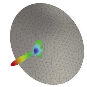 Radiation pattern for a thermally deformed satellite antenna dish, showing solver mesh, calculated with CST MICROWAVE STUDIO. The change may be small compared to the pattern for the unstressed version, but it may be enough to cause signal problems at the edge of the satellite’s footprint.
STAR-CCM+. The result is detailed thermal data vs. geometry, with easy-to-rerun solver templates that can be reused to evaluate design changes.
Stefan Holst, a CD-adapco electromagnetics (EMAG) application specialist, says one of the benefits of working on the front end with SPEED is that users can import CAD geometry with the properties already defined by the electrical engineers; this includes files generated in such design packages as CATIA and losses calculated in other EM packages. Holst explains that for a detailed thermal analysis, mechanical engineers should address the facts that material properties can be anisotropic, heat losses are not homogeneous (copper losses are non-linear and temperature-dependent, for example), and skin effects require problem-specific setups for meshes and solvers. At the same time, many CAD model details can be simplified without loss of accuracy in the thermal results—for example, wires wound in a coil represented as a solid copper strip.
Simplifying CAD Integration
For more than 20 years, Remcom EM simulation and wireless propagation tools have supported MP analyses across a broad frequency spectrum. The company’s flagship XFdtd package applies a time-domain/frequency-domain approach (explained at Remcom.com/xf7-fdtd-method) that scales with problem size; it’s particularly effective at simulating non-linear materials. Fast processing speed is supported on NVIDIA compute unified device architecture (CUDA)-enabled graphics processing units (GPUs) and message-passing interface (MPI) clustering.
Acknowledging the need for smooth CAD integration and efficient design processes, Remcom developed its CAD Merge feature about 10 years ago. Scott Langdon, Remcom co-founder and president, describes how this feature was originally developed for mobile device manufacturers working with rapidly changing mechanical design files.“Mobile device CAD files may have thousands of parts, and the antenna design engineers would sometimes spend an hour or more assigning electrical properties—which are typically not part of a CAD file—to perform accurate EM simulations,” he explains. “Also, they would sometimes make other changes, such as regrouping parts related to the various antennas. The problem was, slightly updated versions of the CAD files would frequently become available, requiring the design engineers to again perform these material assignments and grouping operations on the new CAD file.”
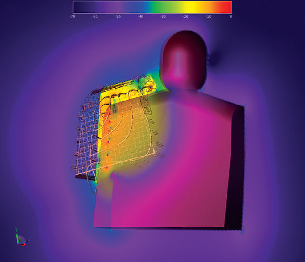 Electromagnetic radiation analysis of a deep-heating therapeutic shoulder garment from ReGear Life Sciences, calculated with Remcom XFdtd electromagnetic analysis software.
Image courtesy of Remcom.
With CAD Merge, design engineers can perform an initial round of setting up material properties and parts hierarchy, and XFdtd will save it. When a new file is available, CAD Merge compares the two files to see what’s the same. It then identifies new and deleted parts, and, for all unchanged parts, arranges them precisely as before with the same properties, quickly and automatically.
The XF7 Assistant in XFdtd is another productivity Remcom tool that eliminates redundant tasks. With XF7, users can turn a project into a template, store parts in a shared library, and save simulation for comparison. It also guides users through each step of a project setup, toggled on or off as desired, without the fixed sequence of a traditional wizard.Few software companies with EM design and analysis products can say they’ve been in this arena almost 40 years, but that situation holds at Infolytica, founded in 1978. The company’s first product, MagNet, has evolved from a basic 2D analysis system to a full 3D EM modeling program that is available standalone or totally embedded in SolidWorks. MagNet, along with ElecNet, Infolytica’s electric field simulation software, now supports multicore mesh generation, solvers and post-processing.
Links to third-party software such as Matlab and Excel simplify automating MagNet and ElecNet model creation and post-processing, while both packages couple directly with Infolytica’s ThermNet for steady-state and transient thermal simulations and OptiNet for automated design optimization. The Infolytica website lists a wide variety of applications, from loudspeaker and maglev system design to optimization of magnetrons and die-press equipment; many examples include helpful videos and even downloadable model files.
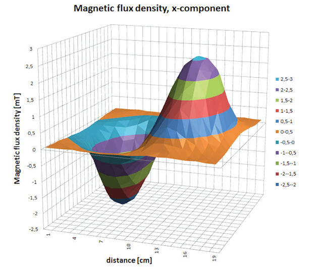
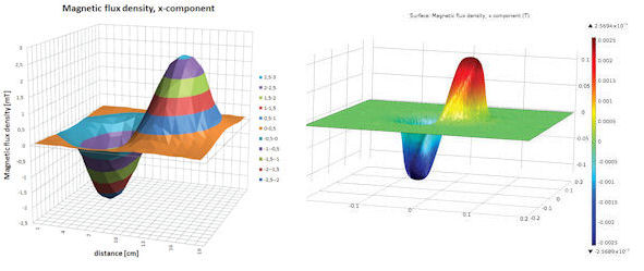 Measured (left) and simulated (right) images of x-component of magnetic flux density for coil design of a Miele inductive-heating stovetop, performed with COMSOL Multiphysics software. Image courtesy of COMSOL.
If you prefer working exclusively with CAD-integrated packages, look into ElectroMagnetic Works software. Its seamless integration with either SolidWorks or Autodesk Inventor eliminates the need for geometry import. Based on FE methods, the company’s EM and magnetic software products—EMS, HFWorks and ATLASS—cover analyses ranging from DC to millimeter-wave frequencies. Sample applications include motors, micro-electro-mechanical systems (MEMS) devices, microstrip conductors, antenna feedhorns, multiplexers and cardiovascular catheters.
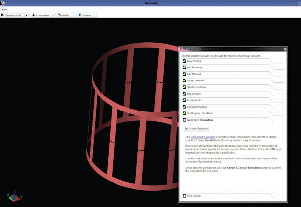 Step-by-step optional XFdtd Assistant tool from Remcom, in support of its XFdtd multiphysics electromagnetic analysis software. Image courtesy of Remcom.
To run an EM simulation, EMWorks users select a study type for running multiple what-if scenarios on a CAD model, then assign materials and boundary conditions. The software performs automatic mesh generation, starts the solver and generates automatic reports as desired. A familiar feature tree displays all tasks; users can drag-and-drop simulations for cloned studies and easily share EMS study results across mechanical, thermal and fluid simulations within the CAD software.
Contributing Editor Pamela Waterman, DE’s simulation expert, is an electrical engineer and freelance technical writer based in Arizona. You can send her e-mail to DE-Editorsmailto:[email protected].
More Info
Subscribe to our FREE magazine, FREE email newsletters or both!
About the Author
Pamela Waterman worked as Digital Engineering’s contributing editor for two decades. Contact her via .(JavaScript must be enabled to view this email address).
Follow DERelated Topics


