

Latest News
February 1, 2006
By Erin Hatfield
The push-start is crucial in Olympic bobsledding. And aside from the pull of gravity that then takes over, the push is all the power allowed in competition. It’s ironic then that the sport’s sled, which has no motor and a deceptively simple aerodynamic functionality, would attract the attention of former NASCAR driver Geoffrey Bodine and his chassis and suspension design specialist Bob Cuneo.
 |
| At a World Cup stop in Lake Placid, NY, this past November, the redesigns paid off with three medals for the men and one for the women. |
But Cuneo wants to improve on that success using computational fluid dynamics (CFD) studies of the two- and four-person sleds for new designs. He sought out the expertise of Capture 3D Inc., Raindrop Geomagic, and Automotive Aerodynamics, Inc. to help create a 3D computer model and perform the CFD analysis.
Sled Design on a ShoestringBy Olympic standards, U.S. bobsledding is managed on the smallest of budgets. From the 1960s to the 1990s, the team raced hand-me-down sleds from European teams that were constantly upgrading their rides. Now the U.S. team designs, tests, and manufactures its own sleds for less than a tenth of the budget of many European teams.
 |
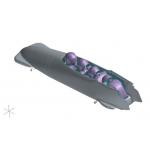
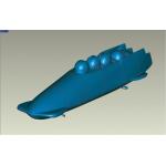
| The sleds were first lifted onto sawhorses so the geometry could be captured from all sides, including the undercarriage. |
“In this age of computer-aided design,” says Cuneo, “]hand forming] was the wrong way to go about it.” He knew he needed to create a 3D computer model for a CFD study, but no native CAD data existed for any sleds. Cuneo needed to capture the sleds and athletes in 3D, create a digital model, and find the right CFD solution.
Windless Wind TunnelLast year, Cuneo attended a roundtable discussion sponsored by the U.S. Olympic Committee that brought together equipment designers from a number of sports and experts from several engineering fields. He met Kim Blair, the head of sports technology at MIT, where new software to analyze low-speed aerodynamics was being developed. Blair wanted to make the software available to the U.S. Bobsled Team.
After that meeting, Cuneo began searching for a company that would scan the sleds with athletes holding their tucked race positions. He had no takers. The problem was that most scanners needed the athletes to remain still, in uncomfortable positions, for the hours it would take to complete a detailed scan. Simply breathing during scanning would repeatedly move the athletes too much for the 50-micron accuracy needed from the scan.
 |
| The bobsled team was scanned in a mere seven seconds while they tucked into the positions they would hold during an Olympic run. |
“The athletes’ participation can’t be duplicated,” says Cuneo. “You can design a superior sled on the computer, but once you put the athletes in, it’s junk because the estimations are wrong.”
According to Cuneo, this is because a bobsled’s aerodynamics more closely match those of a motorcycle than a car. With cars, the vehicle’s body is the main aerodynamic unit. With motorcycles and bobsleds, people are part of the aerodynamics because they are exposed to the environment. Scanning athletes in actual sleds was the only way to create an accurate 3D model of the entire mechanism.
Optical Triangulation-Based ScanningCuneo found the answer at Capture 3D, a scanning solution provider in Novi, Mich. Capture 3D was willing to take on the challenge, and the company knew it had the right equipment to accurately capture the position of athletes and sleds, without requiring the athletes to sit for long periods of time.
 |
| Powder was applied to reduce surface reflection before barcoded identifying markers and circular targets were attached. |
To begin the process, the sleds were lifted onto sawhorses so the geometry could be captured from all sides, including the undercarriage. Then a powder was applied to reduce surface reflection before barcoded identifying markers and flat white circular targets were applied to the sleds to assure the accuracy of the scans.
Capture 3D then scanned the sleds using the TRITOP digital photogrammetry system from GOM mbH. TRITOP records the markers and a scale bar via a high-resolution reflex camera from pre-determined views. These views are bundled together in TRITOP’s software, which automatically recognizes and calculates the x,y,z coordinates using triangulation, and applies scale to the locations.
 |
| For full definition and tighter tolerances, each helmet was scanned individually in the same way as the sleds. |
“A benefit of combining the TRITOP system and the ATOS scanner is increased accuracy on larger objects,” says Steve Albrecht with Capture 3D. “The marker coordinates communicate that there’s only one place for the scan data to go in the final model. Alternative laser scanning technologies would have required us to orient and align a great number of scans by hand—a huge undertaking for a large volume scan like this.”
The non-reflective coating and coordinate markers were also applied to athletes’ helmets. They then tucked into racing position and only had to hold formation for seven seconds as 3D data and marker locations were recorded. Each helmet was then scanned individually for full definition and tighter tolerances.
 |
| Before alignment, the separately scanned helmets were positioned on the surfaced model of the sled. |
Because the coordinates on the helmets were assigned while the athletes were in racing position, each separately scanned helmet was automatically aligned on the final point-cloud model. This digital assembly used enough data collected around the athletes to generate a complete model as if the athletes and helmets were still in the sled.
The combination of the TRITOP system and the ATOS IIe scanner gave Albrecht an accuracy of 50 microns (0.002 inches). The total process required 103 scans, a number that would have been considerably higher had the ATOS scanner not been able to scan such large areas.
NURBS Surfaces in Hours, Not WeeksOnce scan data was collected and aligned from each sled, athletes, and helmets, Albrecht created final STL files, or polygonized meshes, in the ATOS software. The files were then sent to Raindrop Geomagic’s Detroit office to create final surfaced 3D models.
Srdjan Urosev, senior applications engineer with Raindrop Geomagic, imported the STL files into Geomagic Studio. Geomagic Studio automatically generates an accurate digital model from any physical part based on data input from 3D scanners, a process Geomagic calls digital shape sampling and processing (DSSP).
 |
| The ATOS IIe software took the helmet scans, and using the coordinate data collected during the sled scan, aligned them with the helmet locations captured earlier while athletes held their aerodynamic positions. |
Urosev did a quick preview for each sled using Geomagic Studio’s push-button surfacing function. He then cleaned up the data where needed, filling in holes and closing gaps.
Urosev worked on the scan data for the sleds and athletes separately, then merged the scans to create the final models. All of the data aligned instantly using the target registration from the scanning session. He also extracted planes and axes that ran through the base of each sled to use for alignment within the CAD package.
“Typically an application like this would take weeks to reverse engineer,” says Urosev. “With Geomagic Studio, I only spent two to three hours on each model.”
In the end, there were two models of the two-man sled and two of the four-man sled. Urosev compared the final NURBS surface models with the original STL file to ensure tolerance zones were met. The final files were exported as NURBS surface IGES files.
When the software from MIT proved not to be the best fit for Cuneo’s process, he turned to another stock-car racing ally, Louis Duncan with Automotive Aerodynamics of Cornelius, NC.
Duncan used the IGES files from the two-man sled for CFD analysis and sent the results to Cuneo for use in altering the racing sleds. All of the analysis and modifications to the sleds were completed in time for the world trials and competitions in November 2005. Cuneo plans to use the same process for CFD analysis of the four-man sleds after the Olympics.
“We worked non-stop to develop the new sled designs,” says Cuneo. “The design hasn’t changed much, but the modifications we made based on the CFD results have delivered huge returns in competition.”
Exactly what those modifications were, Cuneo would not reveal for obvious reasons. What is obvious is that the U.S. Bobsled Team has medaled in every pre-Olympic competition it has entered since the modifications were made, and the newly tweaked two-man sleds will run in the Winter Olympics later this month in Turin, Italy. The team’s success is an early indicator that the CFD analysis should pay off on the Olympic medal podium.
“With so many factors affecting each sledding run, we can’t guarantee that the team will win each race,” says Cuneo. “But we’re in the best possible position we can be in heading to Turin.”
Erin Hatfield is a freelance writer specializing in the computer graphics, IT, and electronics industries. Send hatfield you comments about this artivle via e-mail by clicking here. Please reference “Bobsled, February 2006” in your message.
Bo-Dyn Bobsled Project
Waterbury, CT
Capture 3D
Novi, MI
GOM mbH
Braunschweig, Germany
Massachusetts Institute of Technology
Cambridge, MA
Raindrop Geomagic
Research Triangle Park, NC
Bonus Photo Gallery
 |
Subscribe to our FREE magazine, FREE email newsletters or both!
Latest News
About the Author
DE’s editors contribute news and new product announcements to Digital Engineering.
Press releases may be sent to them via [email protected].


