

December 1, 2013
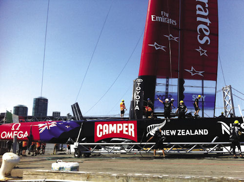 Wing sail and mast structure being mounted between the dual hulls of the ETNZ trimaran America’s Cup 2013 boat. A central pivot structure allows added control in a manner similar to the ailerons of an aircraft wing. Images courtesy of ANSYS. |
The sailing competition, begun in 1851, has seen periodic rule changes that push each new generation to sail faster than before. The latest rules gave way to increased speed and spectator excitement at this past September’s unprecedented series of 19 races over two-and-a-half weeks.
From Wind Tunnels to Workstations
ETNZ’s experience with ANSYS goes way back, with the team initially using FLUENT CFD software in 1998 and then expanding to tap ANSYS CFD software for the boat design of both the 2007 and 2010 cup races.
The 2007 boats were a more traditional yacht design; the 2010 Volvo Cup (America’s Cup Challenger face-off) trimaran boats were a completely different design, notes Gilles Eggenspieler, Ph.D., ANSYS senior fluids product line manager: “And now the 2013 versions are yet a third.”
The trimarans and “hard” (non-fabric) wing sails that first debuted in the 2010 America’s Cup races had hardly been hauled out of the water when the rules were being modified yet again to set the tone for the 2013 competition. Past rules had been formula-based—resulting, for example, in the 12-meter boats, where 12 meters is the maximum value of a formula that combines such design specifications as load, waterline length and area of the sails. This time, the committee opted for a Box Rule, the spirit of which is “as long as it fits inside the box, it can race.” All designs were catamaran-based; hulls became 72 ft. long by 48 ft. wide, and the massive wing sails rose to 134 ft. tall.
For all its copious details, the updated Class Rule, known as the AC72, contained a loophole permitting the use of movable, shaped “daggerboards” or foils that protrude into the water from each hull. Such a feature effectively converts a catamaran into a hydrofoil—elevating the hull out of the water so that the craft “flies” on upwind and downwind parts of the racing route. Supported only by the foils and rudders, and without the drag of water on the hulls, it achieved speeds approaching 51 mph.
With the design crew free to capitalize on the maximum airflow past its sails, both foil and wing design became critical design elements for successful tacking, foiling or rounding of racecourse marks. From the moment this was acknowledged, ETNZ knew their catchphrase would be “controlled flying.”
Design Versatility with ANSYS
The 38-member ETNZ started working on the design of a scaled-down prototype boat in October 2010, in preparation for the July 2013 Louis Vuitton Cup Challenger elimination series.
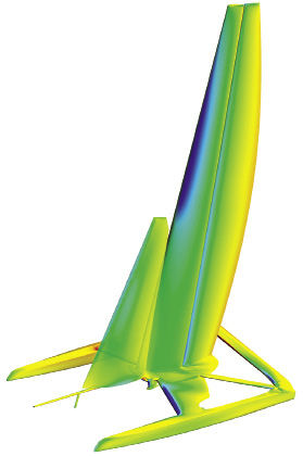 ANSYS CFD simulation of ETNZ’s Cup 2013 boat sailing downwind, showing wind pressure on the structure. |
“The first six months of the project were totally simulation-driven and all our initial concepts were evaluated through ANSYS CFD,” recalls Steve Collie, Ph.D., ETNZ design team member for aerodynamic CFD (sail design). “At that stage, we built small 33-ft. catamarans—the largest prototype allowed under the rules—through which we tested concepts. By October 2011, we launched two identical scale wings for these test yachts, very similar in shape and design to the full-scale AC72 wings we ended up with.”
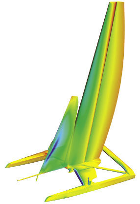 ANSYS CFD simulation of ETNZ America’s Cup 2013 boat sailing into upwind conditions; colors indicate wind pressure on the structure. Analyses must take into account the effects of the airflow coming off the front (head) sail as well as from the mast. Accurate turbulence modeling is critical. |
“Wings” are the best way to describe the curved, carbon-fiber-ribbed 3D sail-structures that are skinned with conformal, nearly plastic sheeting. Think of an airplane wing turned vertical and pivoting about a mast, with the added sophistication of a full-length controllable aileron.
To evaluate hundreds of variables determining the possible wing shape, the design team looked at a wide range of wind conditions. Critical to boat speed is minimizing the drag of the air coming off the headsail (the more-traditional fabric sail in the forward section) as well as from the mast. In addition, when the craft is sailing at a large angle to the wind, stalling is a real possibility. Modeling all the variations of wing geometry vs. operational conditions presented a big challenge in itself, yet Collie knew that this would still only include part of the problem.
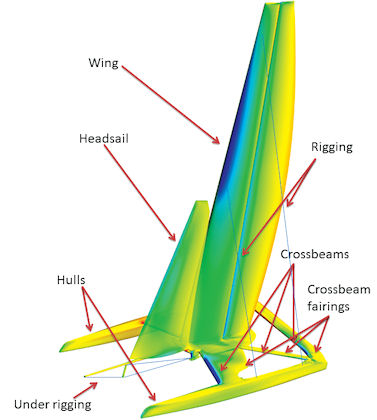 Diagram of primary structural elements important for ANSYS CFD simulation and optimization of ETNZ boat design. |
“There is no point in analyzing the wing by itself,” he notes, “as its aerodynamic performance is dramatically influenced by the headsail and the hulls, crossbeams and fairings. With ANSYS, we’ve modeled the aerodynamics of the yacht, in its entirety, through a massive range of situations that we call the aerometrics. This involves up to 750 different simulations per design of the wing and sails.”
ANSYS CFD software was up to the task of evaluating design improvements with short turnarounds, generally two to three weeks. Inputs included trim parameters for the wing and sails and apparent wind angle. For each iteration, the meshing was 100% automated—which was absolutely key to getting fast results.
“After a matrix of new geometries is transferred to the cluster, a Perl script would automatically mesh, solve and post-process the results,” Collie says. “The output was a text file describing the relevant forces and moments for each point of the matrix. Images were also automatically generated.”
| Rules and the Need for Speed Starting with the 1907 race, America’s Cup rules were developed to ensure both safety and competitive racing. They governed boat size and shape, plus the materials and approaches allowed in support of perfecting a design. They have actually been revised for every one of the 34 Cup races, with just two exceptions. From the moment the U.S. entered a catamaran model (not expressly forbidden), the face of the race changed dramatically. From the trimarans of the 2010 competition to the “flying boats” of this past September’s race, it’s clear that engineering-based ingenuity, including software simulation such as powered by ANSYS CFD analyses, will continue to help Cup sailors rule the waves. —PJW |
Simulations showed when the flow was attached to the wing, and where there was a great deal of interaction with the headsail and the hull, notes Nick Hutchins, ETNZ CFD engineer (wing design). “ANSYS is easy software to use quickly,” he adds. “It’s easy to get good, reliable answers, and from an aerodynamics perspective, the really key technical thing we’re looking for is good turbulence modeling.”
With the earlier, 33-ft. simulated design concepts proven on the water (netting ETNZ the single Cup challenger slot), the design team had the confidence to use 100% simulation for the full 72-ft. craft design. Simulations began Aug. 5, and the boat was built within a month. Further hardware modifications were made in just two days based on additional performance testing, and the craft was ready for racing on Sept. 7.
ETNZ Technical Director Nick Holroyd sums up the power of simulation: “In 16 years, we’ve seen the transition from physical testing, where almost everything we did was done in the wind tunnel or the towing tank, through to this Cup cycle, where we’ve finally managed to get to 100% numerical analysis and digital prototyping. The productivity gains and the extra insight it’s offering us are extremely valuable.”
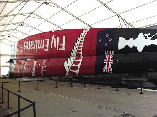 View of the “hard” wing, 134-ft.-tall sail of the ETNZ trimaran boat from the 2013 America’s Cup race, fully simulated with ANSYS CFD simulation software prior to building. The wing is split in two vertical sections, each of which can be trimmed on the fly. Note steps to right for scale. |
In spite of this year’s Cup being won by Oracle Team USA in a come from behind victory (see “The Winning Edge,” page 53) that was ultimately based on a combination of many factors in addition to boat design, ETNZ say they will stay the course on using ANSYS CFD analysis in the future. DE
Contributing Editor Pamela Waterman, DE’s simulation expert, is an electrical engineer and freelance technical writer based in Arizona. You can send her e-mail to [email protected].
More Info
Subscribe to our FREE magazine, FREE email newsletters or both!
About the Author
Pamela Waterman worked as Digital Engineering’s contributing editor for two decades. Contact her via .(JavaScript must be enabled to view this email address).
Follow DE

