

May 11, 2011
By ESI Group
An automobile original equipment manufacturer (OEM) wanted to introduce an existing vehicle into the North American market, but its head impact deceleration was 20% above Federal Motor Vehicle Safety Standards 201 and 201U limits. The OEM hired EASi to re-engineer and redesign the interior to meet an internal target that required reducing deceleration to 20% below 201/201U limits. Traditional manual methods of determining impact zones, selecting impact points, computing impact angles, assigning initial velocities, etc., would have taken about one day per point for each of the 80 points typically needed for a 201/201U analysis. Using these methods, the entire design process, including the lengthy design approval process, would have taken about eight months.
EASi engineers substantially reduced the amount of time required to meet FMVSS regulations by using ESI Group’s Visual-Process development environment to automate most of the 201/201U analysis process. The Visual-Process workflow reduced the time required to set up each of the many possible head impact points for analysis “from one day to just five minutes. The work flow also automated downstream elements of the analysis process, such as creating the input data for crash simulation.
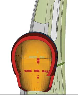 Head form positioned at BPILLAR2. | 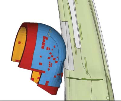 Head form positioned at BPILLAR. |
EASi engineers used these methods to guide the process of evaluating alternative measures for meeting the internal target. The engineers were able to complete the design process, including all approvals, in only five months. Much of the five months was involved in developing the headliner design, developing countermeasures and working with the customer to get approval for the changes “which, of course, cannot be automated.
Founded in 1981, EASi is a global engineering firm that services the U.S., European and Asian markets. EASi has extensive experience in crash and safety engineering. The company has worked extensively with automotive OEMs and suppliers, as well as with the National Highway Traffic Safety Administration (NHTSA) on research and development projects “including safety regulations like 201, 208 and 214.
Held to a Higher Standard
The automobile was previously designed for an overseas market, where head impact standards are less stringent than FMVSS 201/201U.
“The vehicle originally had head impact decelerations well above FMVSS 201 standards,” recalls Ravi Chilukuri, EASi’s engineering services director. “The automotive OEM’s target of 20% below the FMVSS standards was very challenging, particularly considering that design freedom was limited on this existing vehicle by the need to meet styling and packaging constraints, such as maintaining existing Class A surfaces. It was clear from the beginning that we would have to try many different design alternatives to reach the target.”
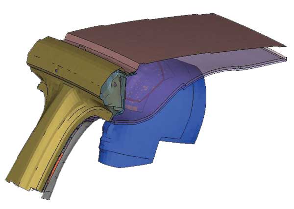
FMVSS 201 states that when an area of the instrument panel that could be impacted by the head in a crash is hit by a 15-lb., 6.5-in.-diameter head form at about 12 mph, the deceleration of the head form shall not exceed 80 g continuously for more than 3 milliseconds. FMVSS 201U provides a similar requirement for upper interior components such as the pillar trim, headliner and grab handle. The OEM or supplier must select the number of representative points for simulation that fall in the calculated head impact zone, and ensure that each point meets the requirements.
 Head form positioned at APILLAR. | 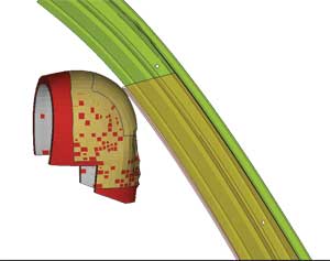 Head form positioned at APILLAR. |
Meeting these standards would have been a very time-consuming process using conventional manual methods. EASi engineers would have worked with CAD software to determine the impact zone, selected representative points within each zone and computed the impact angle for each point. Then they would have needed to position the head form at each impact point, assigned an initial velocity to the head form, created contacts between the head form and the impact point, created input-output control cards, exported LS-DYNA data, read the LS-DYNA results files and created an electronic report of the analysis results. The amount of time required to perform these tasks manually would have driven up the cost of the project “and made it impossible to meet the OEM’s aggressive timeline for entering the North American market.
Automating the Process
“Being a CAE services company, we have had considerable experience in addressing this type of challenge,” Chilukuri says. “We understand the difficulties of doing it manually, and sought out an automated solution that would provide time savings, as well as a repeatable process that could ensure accuracy on every program. ESI’s Visual-Process is the only tool that I am aware of that provides an environment to automate the complete end-to-end head impact simulation process.”
“We know the Visual Process very well, as the genesis of the Visual Process was at EASi 12 years ago,” says Prakash Krishnaswamy, president of EASi. “We are an organization that has always worked toward introducing or developing cutting-edge and innovative CAE technologies to enable CAE-driven solutions to our customers.”
The automated solution is based on ESI’s Visual Decision Support System (VisualDSS), which is designed to build and manage simulation models for multiple domains, automate processes and work flows, manage simulation content and data, and support knowledge-based decisions and automated reporting. This environment captures and automatically executes simulation processes using wrappers for popular simulation and CAD tools. Templates are defined using the Python scripting language, and the task execution sequences can be described through a visual interface. The library of templates can be searched using filters and defined criteria for reuse in new projects.
Visual-Process also interfaces with ESI’s Visual-Crash Dyna software, which enables graphical creation of an LS-DYNA input deck, modification and deletion of contacts, materials, constraints, control cards and crash entities. Visual-Crash Dyna is incorporated into the automated process, and helps ensure that the model is correct before it is submitted to the solver.
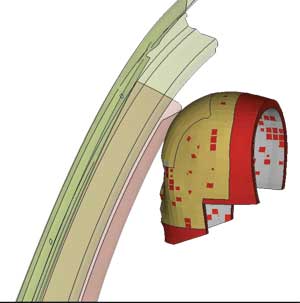
Head form positioned at URBP.
Setting up the Crash Simulation
The OEM provided the geometry of the original design as CAD geometry. EASi engineers needed to establish more precise material properties, so they requested coupon samples cut out of the material used in the interior and sent them to a material testing company. The testing lab determined the stress-strain curves and strain rate-dependent properties. EASi engineers read the CAD data into Visual-Process, and the FMVSS 201 script automatically scanned the CAD file by moving the head model as specified in the regulations to identify the impact zones.
EASi engineers then set up criteria, including starting point and increment, to select the impact points. The script computed the impact angle, and positioned the head form at the impact point. The script assigned the initial velocity to the head form, as defined in the regulations.
The script then created LS-DYNA contacts between the head form and the instrument panel, pillar trim, headliner and grab handle. The script created the LS-DYNA input-output control cards. Engineers reviewed the input data, and made changes such as moving impact points to locations that might be particularly prone to cause injuries. Engineers directed the script to export the LS-DYNA input data, organized all of the resulting models and submitted them for sequential solution on the solver.
The script captured the results of the solver, and produced a report that showed that decelerations in the initial design exceeded the FMVSS standards by about two-thirds. These results matched physical testing, and provided the confidence needed to move ahead with using the model to redesign the interior.
Iterating to an Optimized Design
“We then went through a series of design iterations to develop countermeasures to meet the internal target,” Chilukuri recalls. “We tried a variety of different methods for each point, depending on the packaging space that was available for absorbing the energy of the head impact and other design constraints. These included molded-in ribs, energy absorbing cones and foam. We had to address some complex interactions; for example, putting in an energy cone slows the velocity of the head form. This reduces deceleration, but also limits the distance that the head can travel, which in turn increases deceleration.”
Some of the design changes changed the shape of the surface, Chilukuri says, which in turn changed the location of the contact point and made it necessary to go back and run the analysis again for the new point.
“Another complicating factor was that some points were close together, so a change that improved one point might have a negative impact on nearby points,” he continues. “We were able to meet the requirements with a single design change on some points, while as many as 10 iterations were required on others.”
However, Chilukuri adds, Visual-Process and Visual Crash Dyna saved time in automating most of the process “setting up the initial model automating downstream tasks in analyzing additional design iterations.
“They enabled us to reduce the time required to set up the model for each point from a day to 5 minutes “a 99% savings “and substantially reduced the time required for each design iteration by automating simulation setup,” he concludes. “The result is that we were able to evaluate approximately 300 different design iterations for the 80 points, and reduce head impact accelerations by an average of 50%, as required to meet FMVSS 201 and 201U regulations. The complete design and engineering cycle took 38% less time than would have been required using conventional methods.
“With the Visual Process, and with our extensive experience in automotive interiors design and engineering, the percentage savings would have been even greater if we had designed the vehicle interior from scratch.”
For More Info
ESI North America
Subscribe to our FREE magazine, FREE email newsletters or both!
About the Author
DE’s editors contribute news and new product announcements to Digital Engineering.
Press releases may be sent to them via [email protected].


