

Latest News
December 12, 2011
By DE Editors
So you’ve finally bought your shiny, new car. But then one day, the noise starts—an unidentifiable, repetitive, distracting sound coming from somewhere inside your vehicle. In no time at all, that annoying sound is driving you crazy.
The problem is called squeak and rattle (S&R), and it’s been driving the automotive industry crazy, too. Paradoxically, while great progress has been made in other areas of noise vibration (N&V), the fact that modern automobiles run more quietly than ever has made lingering S&R issues even more apparent. With engine and road noise diminished, smaller sounds that used to be hidden become magnified to the driver’s ear. While specific S&R issues can be targeted, ongoing trends toward lighter cars and new materials continue to work against total elimination of the problem.
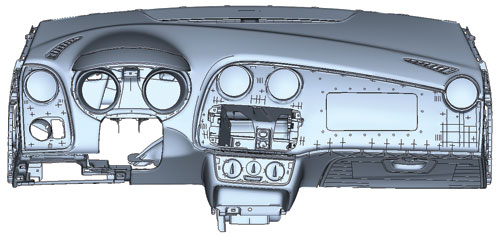
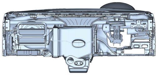
Figure 1. The FE model of front (top) and rear (bottom) of instrument panel
used for the study, courtesy of SEAT.
S&R is often located in the interior trim of a vehicle, such as the dashboard, but the exact source can be hard to pinpoint. “Squeak” happens when components periodically slip and stick together. “Rattle” occurs when parts hit each other intermittently. Both noises usually stem from inconsistent assembly tolerances or lack of stiffness. Some are more detectable at slower driving speeds; others get worse as you accelerate.
When noticed during a test drive, S&R can be seen as a sign of poor quality and durability, putting off potential customers. When S&R issues surface after purchase, they are difficult for car dealers to diagnose and expensive for them to fix. The fixes may even lead to new S&R problems. Subsequent warranty claims can have a significant impact on vehicle manufacturers’ reputations—and profit margins.
A definitive paper on the subject, delivered to the Society of Automotive Engineers’ Noise and Vibration Conference (“Squeak and Rattle: State of the Art and Beyond,” Kavarana and Rediers, SAE #1999-01-1728) in 1999, exhaustively examined the problem, detailed existing methodologies, and concluded that more refined analysis methods were needed. Some years before, IDIADA was formed to support product development in the global automotive industry with design, engineering, testing and homologation services.
Headquartered near its testing grounds in Barcelona, Spain, the global company now has branches throughout Europe, Asia and South America. In 2010, IDIADA won the “Automotive Testing Company of the Year” award from Automotive Testing Technology International magazine.
Simulation to the Rescue
“Squeak and rattle have become of greater concern for us in recent years as more auto manufacturers come to us with these problems,” says In ©s Lama, project manager, design engineering, for IDIADA. “Our customers are asking us if it’s possible to use simulation to identify the potential for squeak and rattle earlier in their design processes, rather than later, when it is more costly and time-consuming to solve.”
As a mechanical engineer with a university concentration in V&N, plus more than a decade working with similar multi-physics issues at IDIADA, Lama is well-versed in using realistic simulation to visualize and predict many of the complex material responses that arise when motor vehicles meet the open road. She and her team have been using Abaqus Unified Finite Element Analysis (FEA), from Dassault Syst mes’ realistic-simulation brand SIMULIA, for years.
“Since we’d already been using Abaqus in vehicle cockpit design and testing for thermal, impact and normal modal analyses, it made a lot of sense to simply develop a new load case for squeak and rattle inside Abaqus,” she says.
The Rattle Ratio
Starting in 2008, the IDIADA team began developing its S&R-specific simulation protocol based on Abaqus. A paper delivered at the 2011 SIMULIA Customer Conference in Barcelona in May presents the latest improvements in this methodology, applied to rattle in a car instrument panel and correlated with real-world testing. The instrument panel (the physical and the virtual ones) were donated to IDIADA by Spanish car manufacturer SEAT and used in the correlation process for validating the methodology (see Figure 1). The FE model had been used in the normal development process of the component (behavior in crash, static and dynamic stiffness analysis and thermal analysis). But the test layout was designed specifically to provoke the rattle in the cockpit, because this phenomenon didn’t appear in normal usage conditions.
Rattle arises when parts collide and the relative movement between them generates noise if the surfaces adjacent to where the impact occurs radiate audible sound. Developing a new load case to simulate such an event required some creative thinking, the IDIADA team learned.
A classic automotive N&V analysis (of the effects of a car engine running, or tires rolling, for example) uses modal theory to predict at what frequencies certain parts of the vehicle will begin to vibrate.
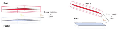
Figure 2. The use of Abaqus connector elements, between volumized, parallel (left)
or angled (right) elements, enabled IDIADA to more accurately evaluate the gap
between the elements—and therefore, the potential for rattle.
“Modal theory is based on the hypothesis of linearity, without contact,” says Lama. “But an S&R event, although it happens within a frequency-dependent, N&V-type setting, is also very non-linear—the parts producing the squeaks and rattles are interacting with each other in three dimensions. A standard, eigenmode-based, N&V method alone can’t model, or predict, the contact that will result in a rattle.”
The engineers needed to come up with a simulation that would accommodate both frequency (N&V) and contact (S&R) behavior. “The unique connector element in Abaqus was particularly useful for us with this challenge,” Lama reports.
Pau Cruz, an advanced Abaqus user of the CAE team, along with colleagues Jordi Vi ±as and Andreas Rousounelos, realized that the connector could be used as a “virtual sensor” for the detection of contact. Placing connector elements in the gaps between nodes in the FEA model of the instrument panel allowed for the measurement of the independent behavior of the model in three different directions. To properly place the connector elements in relation to any two surfaces that might affect each other, IDIADA did a “volumization” exercise (see Figure 2).
While the “virtual sensors” could provide a more accurate idea of the amplitude of movement (“interference”) between two parts, amplitude alone didn’t predict the possibility of rattle, the engineers discovered. The value of penetration also had to be determined—in other words, how much the parts were interfering with each other. In turn, the amount of this interference was affected by the frequency at which the car components were vibrating at various points on the instrument panel (see Figure 3).
Figure 3. Measurement locations on the instrument panel.
For example, low vibration frequencies actually tend to result in higher amplitudes of movement of parts, yet the kinetic impact of any collision would be low. At higher frequencies, parts would actually be displaced less, but the velocity of any impacts would be higher.
Taking all this into account, the IDIADA team determined that the “rattle ratio” had to be calculated as the amount of interference detected scaled by the kinetic energy at the impact time. With this rattle ratio in hand, the engineers could more accurately track the possibility of significant penetration—and hence, the chance of an actual rattle happening—between parts in the instrument panel.
“For a better visualization, you can sweep the frequencies within the whole range of study and see at what frequencies rattle appears with a 2D plot,” says Lama. “Or, you can analyze the most critical frequencies using a 3D plot and, with scripting, create a file with the vector representation of rattle issues.”
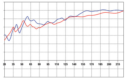
Figure 4. Measured (red) and simulated (blue) frequency response values.
Because the detection of rattle potential in a model is based on an accurate simulation of the frequency response (see Figure 4) of areas susceptible to contact events, the team took particular care to improve the correlation of its FEA models and its real-world tests. The team achieved this by using a Modal Assurance Criterion (MAC) system that looked for similarities and differences in simulation and test values that could be used to help make the models more robust.
By adding more geometric details to the models, including simulation of the masses of the radiators in the heating, ventilation and air-conditioning (HVAC) system, and fine-tuning the stiffness of different connection points, the engineers were then able to pinpoint three areas in the instrument panel that influenced the results the most. These were the two connections of the HVAC duct leading to the two side diffusers, and the connection of the HVAC duct leading to the central diffuser (see Figure 5).
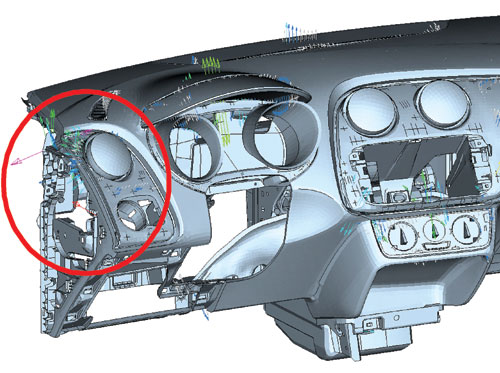
Figure 5. Rattle detected in red-circled area.
Future Implications
The first simulations of these three areas detected rattles with good correlation. Interestingly, the simulations detected many more rattling issues than the real-world tests.
“In the future, we will be working on rattle detection criteria improvement to differentiate between rattles that can be heard and those that can’t,” says Lama. “We will also continue to refine our analyses to include those zones in the vehicle cockpit where there can be more problems with tolerances. At this point, we are beginning to succeed at speeding up the procedure for detecting movement and velocity of impact. Down the road, we will include some kind of tolerance criteria.”
More Info
Applus IDIADA
SIMULIA
Subscribe to our FREE magazine, FREE email newsletters or both!
Latest News
About the Author
DE’s editors contribute news and new product announcements to Digital Engineering.
Press releases may be sent to them via [email protected].


