

February 16, 2015
By Dr. Michael Bak, CAE Associates Inc.
 Dr. Michael Bak, CAE Associates Inc.
I have an old particleboard bookshelf in my office that contains all my heavy engineering textbooks. Over the years, the shelves have sagged more and more under the weight of the books. Since I was not adding additional books to the shelves, what was causing the increasing deformation? The answer is creep.
Creep is the tendency of a material to progressively deform over time under a constant load. Creep is more severe under higher loads and as temperatures approach the material melting point. There are many examples of creep in engineering applications and everyday life: tungsten filaments will creep under their own weight at the high temperatures they experience in a light bulb causing eventual failure of the filament; solder in old lead hot water pipes can creep at room temperature; and glacier flow is the creep reaction in ice that occurs at freezing.
Stress relaxation is a decrease of stress in a material under constant strain. An example is a rubber band wrapped around a newspaper. Over a long period of time, the rubber band remains in the same position, but the force that it applies to the newspaper decreases.
Creep and stress relaxation are related but are not exactly the same phenomenon. Fortunately, it has been demonstrated for most engineering materials that using a creep law defined from material creep data will provide a good approximation of both creep and stress relaxation response, and this approach is a standard structural analysis modeling technique.
Creep can be incorporated into a finite element analysis (FEA) in several ways. The most common approach is using a creep law, which defines the accumulation of creep strain rate as a function of the current stress, strain, time and temperature:
![]()
Creep tests are used to obtain data for a given material, and then nonlinear regression curve-fitting is used to fit the data to the creep law. When performing a creep analysis with this approach, the basic assumption is that the total strain is determined by independently calculating the various strain components, i.e. elastic strain, plastic strain and creep strain, and then adding them together in equation form:
![]()
The following simple test cases will illustrate that adding a creep law to the material response in structural FEA can model both creep and stress relaxation effects. Consider the structural FEA of a straight bar with round cross-section, fixed at one end. The other end of the bar is subjected to an applied uniform static tension load that produces a stress of 2000 psi. A creep law is input that defines the creep strain as a function of stress and time, assuming a constant temperature. The loading is kept constant as the analysis calculates the time-dependent response.
For this first case, the load remains constant over time, and therefore, the axial stress will be constant, since stress is defined as load divided by area. Fig. 1 shows the plot of stress over time for this case, which shows the constant stress state.
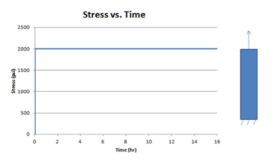 Fig. 1: Constant Load Case — Stress as a Function Of Time
A review of the strain behavior over time, shown in Fig. 2, illustrates several points. First, the elastic strain, which is directly related to the stress, remains constant since the stress is constant. However, since the bar is free to deform over time and creep behavior is included, creep strain accumulates over time, resulting in an increased total strain over time. This case represents a pure creep response.
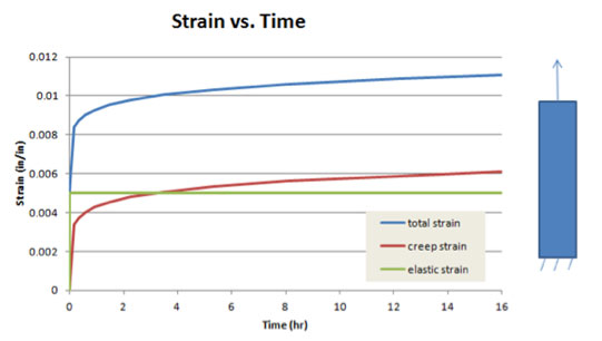 Fig. 2: Constant Load Case — Strain as a Function Of Time
Using the exact same model and creep law, the loading is changed from an applied load to an applied displacement that will produce the same stress magnitude of 2000 psi. After the displacement is applied, it is held fixed in that position and the time-dependent response is calculated.
Fig. 3 contains a plot of stress over time, showing an initially sharp decrease in stress followed by a more gradual decline. This decrease in stress over time for a constant strain case represents pure stress relaxation. Note that stress relaxation is modeled using a creep law with boundary conditions that provide a constant strain in the part.
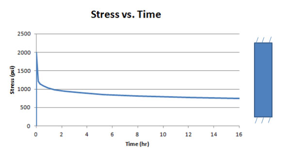 Figure 3: Constant Displacement Case — Stress as a Function Of Time
Fig. 4 contains the strain behavior over time. Since the bar is fixed after the load is applied, the total strain cannot change. However, creep strain is being accumulated based on the creep model, and thus the creep strain increases. Since the total strain is equal to the sum of the elastic and creep strain, and since the total strain is constant and creep strain is increasing, the elastic strain must decrease. The elastic strain is directly related to the stress, so the decrease in elastic strain results in a decrease of stress, causing the stress relaxation.
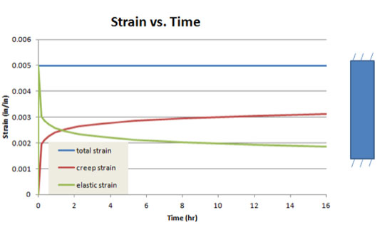 Figure 4: Constant Displacement Case — Strain as a Function Of Time
For the general case of including a creep law in a more complex finite element analysis, accumulating creep strain in the model will result in increased deformation, reduced stress or a combination of both behaviors. If an element is free to deform, the creep strain will produce an increase in total strain. If the element is prevented from deforming, the stress will relax. If the element can deform some amount not equal to the creep strain, a combination of increased total strain and decreased stress will occur. Thus, the modeling of creep in FEA will predict both the creep and stress relaxation response.
Dr. Michael Bak is a senior engineering manager at CAE Associates Inc., an engineering consulting firm in Middlebury, CT. He has over 30 years of experience in finite element theory, linear and nonlinear structural analysis, heat transfer analysis, composite life prediction, fracture mechanics, computer programming and applied mathematics.
Subscribe to our FREE magazine, FREE email newsletters or both!


