

March 29, 2014
p>
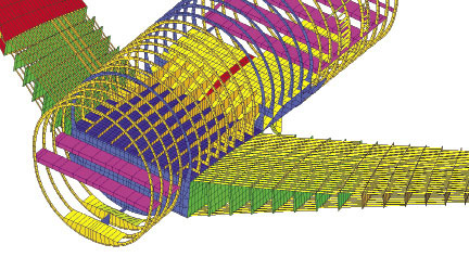
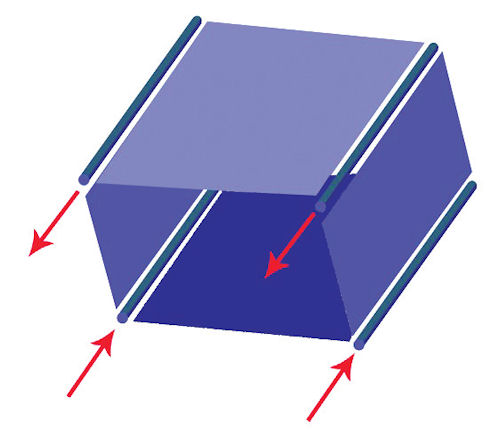 Fig 1: Early shear panel and rod element idealization.
The aerospace industry is one of the originators of finite element analysis (FEA). The company division I worked for in the UK in the 1970s was typical of that time, with roots as an independent aircraft manufacturing company. Our homegrown FEA solution was used on all our aircraft projects. The FEA solver was sophisticated, and met our specific needs. There were six to eight independent FEA solvers in the UK aircraft industry alone; the same pattern was repeated worldwide.
Subsequently, the limitations of an independent FEA solver became apparent. Maintenance, documentation and support were a burden on the engineers who originated the system. Similar problems were found worldwide, with a need for rationalization and compatibility between contractors on many major projects.
For us, the spur to abandon our own FEA solver was the Multi-role Combat Aircraft (MRCA) international project. In the U.S., one of the main drivers for compatibility was the Apollo moon project. Contractors were responsible for building and testing analysis models of their components, which were then combined into a single project model. NASA defined a common specification for FEA data and solution structure, which became NASTRAN. Later, NASA outsourced the development. Commercial FEA solvers are now almost universal.
Idealization Methods
At that time, aircraft and spacecraft FEA models were very simplified representations of the real structure. This was achieved by high level idealization: Fig. 1 shows a typical part mesh. A mix of pure shear panels and end-load carrying rods provide the only load transfer path. However, bending, torsion and axial loads can be carried effectively by this scheme.
A modern-day complaint is that we can’t develop any realistic stresses directly from the FEA model. In fact, the purpose of such a model is not to develop local stresses, but to develop load paths through the structure. Even today, many aerospace FEA models—although they use more sophisticated elements—actually function as load path models, as shown in Fig. 2. The detail stresses are developed from the internal loads found in such a model downstream of the FEA analysis.
There are two main drivers toward this mixed FEA and conventional stressing approach:
- Approximation: The FEA method is a displacement-based solution, and struggles to find an adequately converged stress solution in many cases—particularly when a coarse mesh is used.
- Certification: All primary structures require detailed strength assessment calculations. It was not practical to model large amounts of detail structure using FEA. (Even now, it is problematic to attempt to model a complete structure in detail via FEA.)
Global Modeling Strategy
As noted, many large projects required contractors to combine models in the buildup of the complete aircraft or spacecraft structural model. The super-element technique was developed early on to facilitate this approach. There are two major advantages for this method:
- Each component can be modeled independently by individual subcontractors. All that needs to be shared in the full system model are the mass and stiffness matrix representation and boundary nodal points. This means that each subcontractor can check out his or her own model and share this when ready. The cost of running the final super-element assembly analysis is far cheaper than attempting to run a single standalone model.
- A subcontractor wanting to keep a component confidential only supplies the mass and stiffness terms to the prime contractor assembling the model. The boundary results are passed back to the subcontractor, who solves for the component structural solution locally, but within the context of the overall structural response.
This methodology has become common within the aerospace and other industries for dealing with large structural models, particularly where component confidentiality or autonomy of design is required. However, it does require disciplined analysis setup, which can become quite complex. Most large aerospace companies have evolved this as a “black box” internal process.
 Fig. 2: Model of an aircraft fuselage. Image courtesy of Altair.
An alternative to super-elements is local global modeling. This can provide a bridge between the loads model and a local detail FEA stress model. Forces or displacements from the boundaries of the global model are applied to the corresponding positions in a more highly refined local model. Although this method also has limitations, it is a powerful technique.
At some point in the future, aircraft stress models will presumably use solid element meshing directly of the CAD components. The main attraction will be to eliminate the notoriously complex and time-consuming process of idealization and meshing from solid geometry to shell and beam elements. The downside to this is that models of the order of Giga (10^9) degrees of freedom (DOF) or even Tera (10^12) DOF would be required. This far exceeds the current practical limit for model size.
Fatigue and Damage Tolerance
Fatigue failure is a result of repeated stress application under cyclic loading—often way below yield stress levels. Conventional fatigue analysis identifies stress concentration sites throughout the aircraft using linear static FEA analysis. This can be done with detail models or downstream assessment of a loads model.
The loading mechanism and history applied at the sites are critical, and require careful identification of how compressive, tensile or shear stress states combine. Vibration fatigue analysis may be required on components that see significant dynamic response, such as engine pylons and skins near jet efflux.
Fatigue analysis identifies sites in a structure where crack initiation is likely to occur. The estimate of the fatigue life is based on empirical methods fitted to test data. Fatigue analysis does not, by itself, predict any form of crack growth.
Damage tolerance assessment, on the other hand, can predict crack growth. Potential crack initiation sites are identified, and various crack shapes and sizes are assumed. Linear elastic fracture mechanics coupled with FEA solutions are used to estimate crack growth. The principle is straightforward; however, the challenge is in meshing a crack in a 2D shell or 3D solid model and then allowing automatic re-meshing of the growing crack.
Damage tolerance assessment requires a high level of mesh refinement in a local detail model. Specific sites of interest have to be selected—there is no overall process to sweep through a complete aerospace model.
Loads Derivation
Loading environments vary considerably across aerospace applications. Military aircraft sustain high G maneuvers across all corners of the flight envelope. Also, there may be many variations in external payload and fuel state that have to be assessed, with particular dynamic environments from gunfire or store ejection.
The critical cases for civil aircraft include gust response and dynamic landing. Variations of payload and fuel state must be accounted for—and each possible phasing and positioning of the aircraft in the gust and landing conditions has to be assessed. There may be hundreds of thousands of load cases to be used in assessment of the structural integrity of all components of aircraft. The sheer quantity of load cases demands specific processes to handle this volume of data and stress analysis.
Launcher and satellite structures see high inertial loading during the launch. This occurs together with a harsh dynamic environment, with random vibration loading forces being transmitted from the rocket motors up through the structure. A great deal of effort is spent on ensuring strength and fatigue life.
Aerospace vehicles are subject to aerodynamic loading. Until fairly recently, most of the loading data was calculated from wind tunnel results or well proven classical solutions. As structural configurations have become more complex and performance requirements more demanding, however, a need for greater fidelity in aerodynamic calculations has evolved: Computational fluid dynamics (CFD) now plays a vital role in modern aerodynamic simulation and loads derivation.
For initial calculations, a wing or control surface is assumed to be rigid under aerodynamic loading. However, the wing is flexible and will change its configuration with resultant perturbation of aerodynamic loading until a balanced state is reached. Steady aeroelastic FEA calculates this interaction, and allows a modified aerodynamic loading distribution to be used.
Unsteady aeroelastic analysis calculates the dynamic interaction between an oscillating airflow and a vibrating control surface. A search is carried out for critical flutter modes across the aircraft flight envelope. (Flutter is an extremely dangerous phenomenon, and is usually catastrophic.)
Both steady and unsteady aeroelastic analysis traditionally used linear structural analysis, basic aerodynamic panel methods and simple load models to develop the required dynamic interaction. However, these methods cannot deal well with structural non-linearity, complex 3D vehicle shapes, transonic flow or highly localized flow.
There is now a move to couple more accurate CFD calculations with structural calculations using fluid structure interaction (FSI) methods. UAVs can have highly flexible wings and FSI permits coupling non-linear structural analysis with CFD. The main issue here, however, is that the CFD calculations are expensive compared to structural calculations.
Thermal loading and analysis are required for structures near engines, rocket motors, etc., as well as kinetic heating of the airframe from high-speed flight. This may be done fully within an FEA solution, or an independent thermal solution may be mapped or coupled to the structural FEA.
Composites
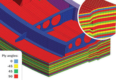 Fig. 3: A 3D solid composite. Image courtesy of Altair.
The biggest change in aircraft design over the past 20 years has been the dramatic increase in the use of composites for primary structures. Test programs and techniques have developed to provide the supporting evidence for strength and stiffness assessment. Similarly, simulation methods have evolved to handle a new type of structure (see Fig. 3). This has been a steady evolution from classical laminate theory mapped into thin shell applications.
This works well for continuous structures such as wing and fuselage skins. However, for joints and more complex (and typically, heavier) fittings, local effects become important in a composite layup. In this case, 3D solid elements are used that allow full interlaminar and through-thickness effects to be simulated. Failure modes such as delamination and interlaminar shear would otherwise be missed.
The actual failure mode of a composite structure can be a challenge to assess. Even a simple coupon test, subject to compression and shear, results in complex microlevel failure that is not well represented by traditional failure theories. If the real structure is a skin-to-stringer joint at the edge of a panel, it can be difficult to predict failure. FEA techniques are evolving along several fronts to try and deal with these situations.
Phenomenological failure criteria attempt to predict distinct failure modes that are strongly dependent on loading action. These replace the more traditional failure criteria. For example:
- Progressive ply failure degrades the stiffness properties of plies within a layup to allow a more gradual loss of strength as load is increased.
- Cohesive zone elements attempt to model the bond line failure between plies, using local bond separation forces and displacements.
- Virtual crack closure technique (VCCT) methods model bond line and possibly ply matrix failure using a fracture mechanics approach, to assess crack propagation under loading history.
- Micromechanics analysis of failure modes in localized regions is mapped to the global FEA model to improve the fidelity of the failure modeling.
New Analysis Areas
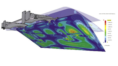 Fig. 4: Management-based Design for Environment (MbDfE) co-simulation of a wing flap mechanism. Image courtesy of MSC Software.
In addition, there are structural analysis techniques becoming increasingly important within the aerospace industry, including:
- Multi-body dynamics analysis (MBDA) deals with mechanisms made up of rigid components. The technology has been extended so that flexible bodies created from FEA can be coupled into the MBDA. In the past, structures such as flaps (see Fig. 4) were analyzed in separate configurations. With MBDA, multiple configurations can be introduced—as well as the dynamic interaction with the surrounding structure. Whole vehicle applications in gust or dynamic landing scenarios look promising.
- Non-linear analysis has not traditionally been used, as structures are expected to show adequate margin over limit conditions. However, in the drive for ever-lighter structures combined with the strength-to-weight ratio of composites, post-buckling analysis of structures that are allowed to develop wrinkles or moderate buckling below limit load is being explored. Some radical designs of UAV, space sails, etc., require large deformation analysis, for example.
One of the biggest challenges is to be able to harness this level of model fidelity, and use it effectively within the traditional strength assessment requirement for the whole vehicle structure. At some point in the future, there will be a migration to solid-element, full-vehicle modeling that will require a rethink of the whole process.
Subscribe to our FREE magazine, FREE email newsletters or both!
About the Author
Tony Abbey is a consultant analyst with his own company, FETraining. He also works as training manager for NAFEMS, responsible for developing and implementing training classes, including e-learning classes. Send e-mail about this article to [email protected].
Follow DE

