

Latest News
October 1, 2011
By Jason Foulger and Brad Allen
Non-linear finite element analysis (FEA) has proven to be an indispensible tool in the development of elastomeric molded shapes and seals. FEA models provide the ability to observe the behavior of elastomeric parts or seals when subjected to external forces. These models can then be used to investigate the validity of proposed solutions without lengthy, expensive prototyping and application testing.
Parker Hannifin’s Engineered Polymer Systems (EPS) division was asked to design and manufacture a series of flexible boots from Parker Resilon polyurethane to protect the sensitive joints of down-hole drills used in the oil and gas markets. The purpose of these boots is to protect against adverse conditions that could result in seizure, breakage or decrease in torque transfer. The polyurethane material provides additional wear-and-tear resistance over traditional rubber boots.
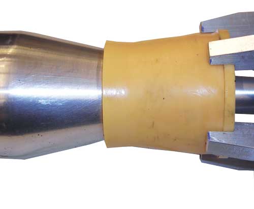
Figure 1: The flexible boot installation tool.
One of the challenges faced by the design engineers was how to install the tight-fitting boot onto the joint for service. To solve this problem, a custom tool was designed to stretch and install the boot onto the joint (see Figure 1). The installation tool consists of a fixture with five pivoting fingers, designed to push against the heel of the boot and drive it over a tapered, lubricated cone.
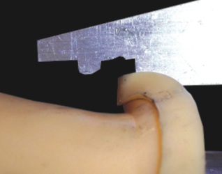 Figure 2: The original tool design shows how the heel rolls over just before the boot loses contact with the fingers. |
Because the fingers are allowed to pivot, contact between the fingers and the boot’s heel is maintained as the boot is stretched radially over the cone. A tensioned rubber band is used to provide inward radial force on the fingers to keep them close to the cone. Once the boot reaches the end of the cone, it can be slid into position over the joint.
The installation tool proved successful with several boot designs; however, a challenge was encountered during the installation of a particularly small boot with a thin cross-section. Once it reached a certain point along the cone, the boot’s heel would rotate outward—causing the fingers to slip off and preventing installation (see Figure 2). The boot’s thin cross-section was not sufficiently stiff to avoid buckling under the installation force. Several immediate ideas, such as adding more rubber bands around the fingers and adding more lubrication to the cone, did not solve the problem.
FEA to the Rescue
An axisymmetric FEA model was created (using MSC.Software’s FEA application) to simulate the conditions of the boot installation. The Resilon material was characterized for use in the FEA model via simple tension and compression testing. The resulting stress-strain curve was then fit to the non-linear, hyperelastic Ogden material model. The Ogden strain energy function is![]() , where1,2,3 are stretch ratios and ±i andi are specific material constants unique to the Resilon polyurethane. The above function is in its original incompressible form. The actual function implemented in the FEA program involves a bulk modulus term to account for near incompressibility.
, where1,2,3 are stretch ratios and ±i andi are specific material constants unique to the Resilon polyurethane. The above function is in its original incompressible form. The actual function implemented in the FEA program involves a bulk modulus term to account for near incompressibility.
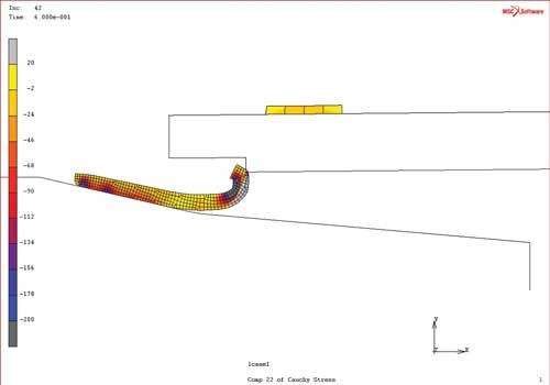
Figure 3: The FEA model predicts the outward rolling of the boot’s heel and the subsequent loss of contact with the installation tool.
The cone and fingers of the installation tool were assumed rigid because the deformation in these metal components is relatively small compared to that of the elastomer boot. A coefficient of friction was applied between the boot and cone that approximates lubricated contact. As illustrated in Figure 3, the FEA model accurately replicated the installation failure.
Design Optimization
At this point, these FEA results were used as a benchmark against which proposed solutions were evaluated. A cost-effective—and more importantly, quick—solution was needed. Two ideas for modifying the cone were examined in FEA: using a single taper instead of the dual taper, and lengthening the cone to provide a smaller taper angle.
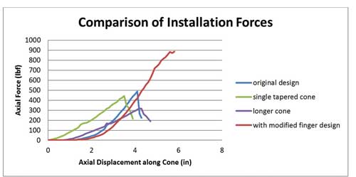
Figure 4: Axial force as a function of the boot’s position along the cone. Only the design with the modified fingers could support the installation force without buckling.
The model predicted little or no improvement from either of these solutions. In each of the trials, once the applied axial force reached somewhere between 300 and 500 lbF, buckling occurred. This is represented in the drop-off in force of the first three curves seen in Figure 4.
Finally, it was proposed that cutting a groove into the fingers where the boot’s heel would be inserted would allow the fingers to “grip” the heel, and prevent it from rolling outward. The FEA model supported this solution (see Figure 5). The modified design allowed for the boot’s heel to be supported at the high axial force required to drive it up the cone (see Figure 4). This design change also returned the lowest cost and fastest turn-around time.
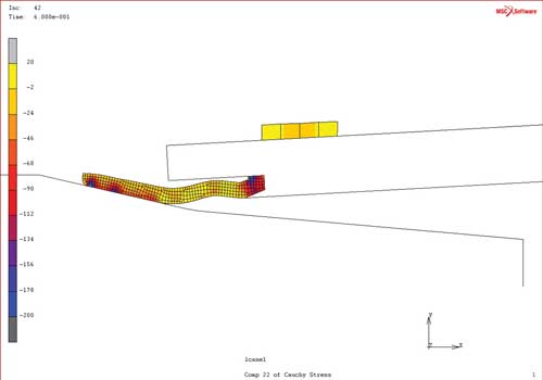
Figure 5: FEA suggests that adding a groove to the fingers will prevent the heel from rolling and allow for proper boot installation.
The new fingers were machined per design changes recommended from the analysis. The tool was reassembled, and the boot installed without problem. The elastomer was monitored throughout the process. Figure 6 shows the elastomer securely contained in its groove. Physical testing successfully validated the FEA predictions.
In conclusion, non-linear FEA provides the ability to confirm the design problem and to perform design iterations quickly until an optimized solution is found. In this case, a simple geometry change to the fingers was all that was needed. Time and money were saved because excessive prototype machining and testing could be avoided.
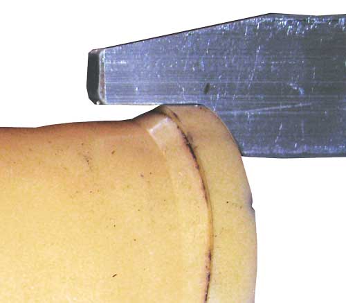
Figure 6: The new finger design, per FEA recommendations. It’s shown at the same position the original design would have lost contact with the boot.
Foulger is a design engineer and Allen is a lab manager for Parker Hannifin’s Engineered Polymer Systems division.
For More Info
Subscribe to our FREE magazine, FREE email newsletters or both!
Latest News
About the Author
DE’s editors contribute news and new product announcements to Digital Engineering.
Press releases may be sent to them via [email protected].


