

September 1, 2010
By Pamela J. Waterman
Converting scanned data-points into organized, dimensioned—dare we say intelligent—shapes is the job of visualization software packages, each with its own approach to data manipulating, storing, editing and sharing. Point-cloud processing extracts geometric information from files holding millions of points, some or all of which are critical for CAD designers, analysis engineers and inspection teams. Each group has different end needs, so for processing software to offer the best value, it has to be well matched to the task at hand. (See “Where Do You Stand on the User Spectrum?” sidebar.)
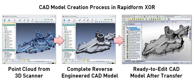 There are three stages to using Rapidform XOR3 point-cloud processing software for capturing part geometry and creating a 3D CAD model. In this example, parametric features are transferred directly into a SolidWorks file. Image courtesy of Rapidform |
DE did its own scan of this field, identifying movers and shakers with offerings that cover 3D CAD file creation, customized inspection and the spectrum of tasks in between. The differences lie in both the target market and the features offered at a given price point. We’ll give you pointers on making a good match.
Part I of this article covers three well-known packages from InnovMetrics Software, Geomagic and Rapidform; each run about $20,000. In the October issue, we’ll cover eight more value-rich packages that may also be a good fit for your job.
Big Three Visualization Tools
Virtually every 3D-digitizing hardware system comes with some level of point-cloud processing software. Think RapidWorks surfacing software bundled with a NextEngine scanner, or FARO’s proprietary CAM2 measurement and inspection capabilities supporting its Laser ScanArm. But for high-end, standalone processing, users and consultants generally consider the Big Three to be Geomagic Studio and Qualify, InnovMetric Software PolyWorks and Rapidform XOR3.
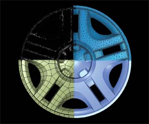 A composite image created in Geomagic Studio shows the various modes of operation during the steps of point-cloud processing: scanned points, polygon mesh and a choice of working with surfaces or solids. Image courtesy of Geomagic |
Each has a reputation for a certain area of strength, yet all now tackle both reverse engineering and accurate inspection in ways that were just ideas even three years ago. (See “What’s Driving 3D Digitizing?” DE August 2007.) The power of classical surfacing, with its fine level of detail, is now meeting the speed of rapid surfacing with its ability to quickly produce usable files.
Todd Grimm, a consultant in the additive manufacturing arena who also follows the scanning world, sees a real convergence in the field, particularly in user interfaces.
“You have to dive deep into the software to distinguish among the three,” he says.
Until a few years ago, reverse engineering software basically connected scanned data points to create a watertight triangular mesh. Users would manually or automatically fit surfaces to this mesh, exporting either an STL faceted file to a 3D printer or an IGES file, or a series of non-uniform rational basis spline (NURBS) surfaces to a CAD program. To continue in CAD software, users would take the curves and surfaces as templates for designing a true 3D model with meaningful, editable features.
Marty Chader, Rapidform’s vice president of business development, calls this approach second-generation technology because the processing software mostly captured the shape of the scanned item as a “dumb” part with little engineering information. However, since 2007, Rapidform’s XOR software (now XOR3) has moved into third-generation performance, offering geometry creation with aspects of true parametric modeling. This approach eliminates the meshing and surfacing steps by modeling solids directly on the points and creating intelligent features. Users can still do 2G mesh and surface fitting, but can also capture such design intents as extrude, revolve, sweep and loft based on 3G design parameter extraction of arcs, lines, etc.
XOR3 software uses a one-step, “live-transfer” process to send the model, feature by feature with automatic assembly, in a native format to standard CAD programs. The process, deemed “the fastest path to CAD,” includes more than 20 feature types—along with the modeling history and any designated feature constraints. For users who still work with NURBS, a new automatic surfacing algorithm speeds up generating surfaces from polygon meshes.
However, there are other ways to address both inspection and reverse engineering tasks when dealing with extremely complex details. InnovMetric Software calls itself “your one-stop 3D metrology partner,” and its PolyWorks software fits that bill for both user groups. The package uses a progression of steps that logically splits tasks between the cloud-processing software and the user’s CAD package, mindful of what makes for the most efficient approach.
InnovMetric president Marc Soucy cautions users to seek practical capabilities when looking to improve the full process from data capture to CAD model building.
“In the next major PolyWorks release, V12, we will offer a sketcher that produces fully parametric editable 2D sketches,” he says, adding that in his opinion, creating a fully editable 3D model within point-processing software is not optimal for two reasons:
- As soon as users get into complex models involving such CAD operations as Booleans or blends, these functions do not transfer; only simple models do.
- While you could geometrically edit the curve that defines a hole, the associative features found in CAD packages are not created along with it (e.g., automatically applying intelligence to rescale a hole).
Where Do You Stand on the User Spectrum? Is the model likely to be changed? If you are scanning Michelangelo’s Pieta, the answer is no, but if it’s an engineered part and you want to perform finite element analysis or another analysis, then the mesh model—a verbatim capture of the shape—is the desired result. (Although the question arises: “Are any changes likely to result from your evaluation?”) If the user wants to physically recreate the object verbatim, then either a mesh or a NURBS surface serves as input to the various additive and subtractive manufacturing processes (e.g., a 3D printer and computed numerically controlled, or CNC, machine). If the intent is to create an editable CAD model, there are two more choices: Do you want to recreate the scanned object along with any flaws (originating from either the scan data or the physical model itself), or do you want to create the idealized model as the original designer had intended? Once you’ve defined your goals, you’re ready to ask companies how they meet them. |
Soucy says he believes his product’s job is to optimize the geometry on scan data, taking care of tasks that are crucial to his full range of customers. For engineers, PolyWorks generates the quad meshes that finite element analysis (FEA) professionals require. For CAD designers, PolyWorks focuses on extracting the freeform elements of a surface for downstream reverse engineering in the user’s preferred modeling package. And for inspection teams, PolyWorks’ high level of sophistication is well known, offering such advanced functions as tracking part variations with statistical process control.
Sometimes a company’s tagline is truly a good clue to what you’ll find in its software. Geomagic touts “the magic of making it simple” for both its Geomagic Studio 12 (reverse engineering) and Geomagic Qualify 12 (inspection) packages. In fact, improving the user interface was a major goal for these latest releases, says Studio Product Manager Kevin Scofield, and the main reason behind adopting detail-rich, ribbon-based windows. Customers (split about 50/50 between the two packages) are discovering “new” functions, he explains, that were actually already in place but not readily found.
For example, to help create a CAD file from scanned data, the previous function “Fashion” is now expanded as “Parametric Surfaces.” It examines a part and identifies logical regions such as holes, extrude faces, etc.; interprets areas as planes or cylinders; performs automatic trimming and creates surfaces that a CAD package can recognize. Users can then choose “Parametric Exchange” and send each element to one of five CAD packages (NX, CATIA, SolidWorks, Pro/ENGINEER and AutoCAD), where the regions are connected into parts and dimensions will be assigned. For more organic shapes, AutoSurface performs one-click surfacing.
Partial fill, bridging across a gap, and interactive modes are supported, while the “Mesh Doctor” finds and repairs such anomalies as spikes, in a single click—for Qualify as well as Studio. A downstream bonus is the ability to generate interactive 3D objects in a PDF report for improved team collaboration. One popular end-use is creating scan models of large areas such as factories, bridges and buildings, not often handled by other packages.
Another Angle to Meshing
In the above discussions, surface smoothness is generally categorized as Class B for NURBS results, with some packages capable of Class A for meshes. There is crossover, however—such as when you maintain curvature continuity while surface modeling, as in Rapidform’s XOR-generated surfaces.
Beyond the scope of this article is software defining the fine-finish surfaces necessary for true automotive Class A. Software in this group includes packages from Siemens PLM Software, whose NX 7 software now incorporates the old Imageware capabilities; Autodesk, with its Alias family of surfacing software; and Dassault Systèmes, who some years ago bought the ICEMsurf product line and incorporated its functions into the CATIA Shape Portfolio.
If a CAD model is your goal, ask each vendor in what form the model will export to your software—as well as at what level of complexity and with what solid-model intelligence attached. Ask about training, too: Sophisticated software requires a learning curve, not just wizards (just think how long it takes to discover the capabilities that lie deep in feature-laden Photoshop).
And remember, companies always stress what they can do, not what they can’t. Even InnovMetric’s Soucy sums up the search process with, “Benchmark, benchmark, benchmark. Do not blindly trust vendors.”
More Info:
Autodesk
Dassault Systèmes
Geomagic
InnovMetric Software
Rapidform
Siemens PLM Software
Contributing Editor Pamela Waterman, DE’s simulation expert, is an electrical engineer and freelance technical writer based in Arizona. Contact her at [email protected].
Subscribe to our FREE magazine, FREE email newsletters or both!
About the Author
Pamela Waterman worked as Digital Engineering’s contributing editor for two decades. Contact her via .(JavaScript must be enabled to view this email address).
Follow DE

