How to Make it in CAD Modeling
Go from 3D scan data to a parametric CAD model, step by step.


Latest News
October 1, 2011
By Rachael Dalton-Taggart
In the past, it’s taken a fair amount of expertise to go from a point cloud—the initial result of a 3D scan of a physical object—to an accurate 3D digital model that is completely editable in a CAD program. But steady progress over the last 10 years, aided by two recent breakthroughs, has created a data freeway originating from the point cloud.
Point cloud processing closes the loop between the physical and digital worlds, providing the physical-digital match that cannot be obtained with a nominal CAD model alone.
Until recently, the most tenuous part of the physical-digital loop was making the connection between 3D scan data and parametric 3D CAD models. Over the past two or three years, however, that connection has been simplified and streamlined by two major developments.
One is the ability to capture and reproduce design intent for a physical object. Design-intent modeling extends reverse engineering from simply producing an accurate digital copy to extracting the original design intent from a scan of a physical model. This ability to generate CAD-ready surfaces from scans of physical objects laid the groundwork for another development: a technology dubbed parametric exchange.
Parametric exchange completes the software bridge between point clouds and CAD. It provides an intelligent connection with CAD to enable automatic native reconstruction of geometry. With parametric exchange, parametric surfaces, datums and curves can be transferred from point cloud processing software to 3D CAD software without the need for intermediate neutral files such as IGES or STEP.
The parametric exchange process leverages the specific strengths of point cloud processing software and CAD software. Point cloud processing software organizes and processes point cloud data to create CAD models, and CAD software enables users to further modify and prepare models for product design and manufacturing.
How it Works
We can see how the process works with this step-by-step illustration. The parametric exchange functionality within Geomagic Studio reverse engineering software works directly within many 3D MCAD systems, including CATIA, Autodesk Inventor, SolidWorks and Creo Elements/Pro (formerly Pro/ENGINEER), to recreate what was 3D scan data and turn it into CAD data. It also uses a range of tools to identify standard elements (cylinders, cones, planes, etc.) based on the point cloud data.
In this example, we will illustrate the process of transferring a 3D model from Geomagic Studio into Creo Elements/Pro:
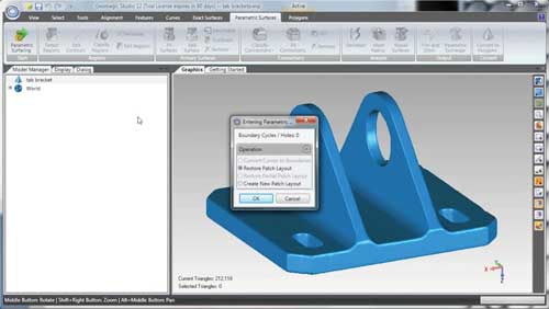
Figure 1: Inside Geomagic Studio, there is a Parametric Surfacing module in the top toolbar. This recognizes discrete features in the model that will be recognized in the MCAD software. The software allows the user to combine and split regions in the model to match the engineer’s needs for the CAD model.
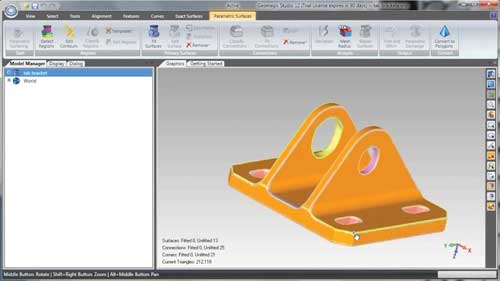
Figure 2: Geomagic Studio then automatically classifies the 3D shapes into distinct features. The user can also manually classify elements by hand (cylinders and extrusions, for example).
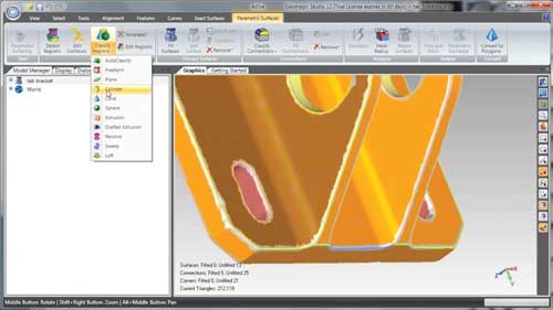
Figure 3: The software then automatically recognizes the edges and creates distinct parametric surfaces for each element.
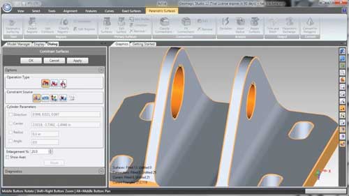
Figure 4: Using the tools within Geomagic Studio, the engineer can then align and constrain elements in the 3D model in preparation for transfer to the MCAD system. The profiles of each extrusion can be individually edited if needed, to build even more accuracy into the data.
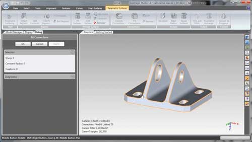
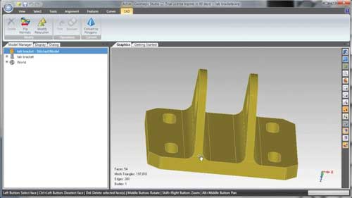
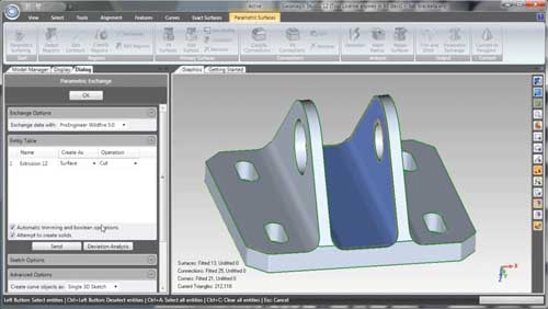
Figure 5: The Fit Connector tools automatically trim the surfaces to ensure the model is completely watertight. The software then stitches the surfaces together. At this point, the engineer is ready to use Geomagic’s parametric exchange tool.
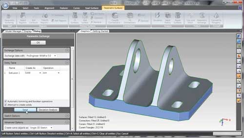
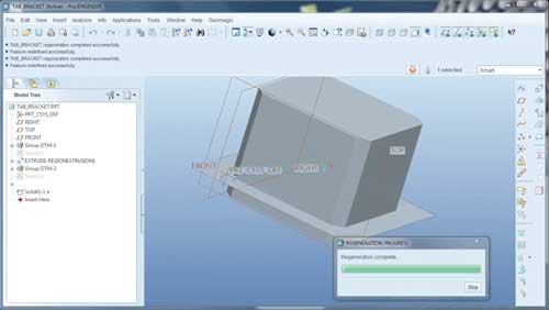
Figures 6 and 7: The engineer selects the base extrusion and sends it automatically to the MCAD system.
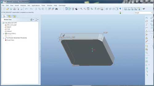
Figure 8: The engineer can switch back to Geomagic Studio and select the cutting pane for the extrusion, and send this to the MCAD system.
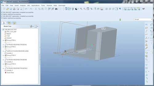
Figures 9, 10 and 11: These steps can be carried out step by step or simultaneously in Geomagic Studio’s parametric exchange.
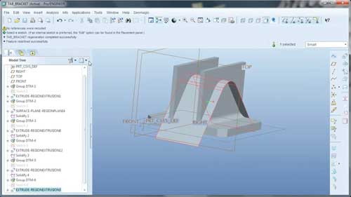
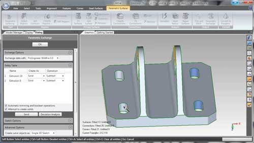
Figures 12 and 13: Slots in the 3D data are selected and automatically transferred to the MCAD system to complete the model.
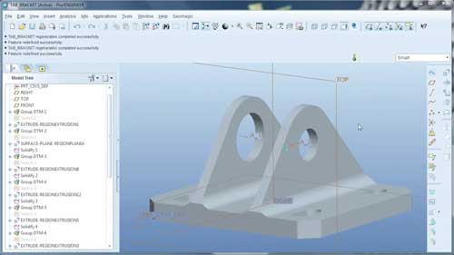
Figure 14: It is now ready as a parametric model for design edits, additions and updates.
Explore, Customize, Analyze
The closed loop between scan data and CAD that parametric exchange provides gives product designers and engineers the freedom to explore new and endless variations of products. Think of thousands of permutations of classic Nike shoes, individualized Mattel toys or personalized fuel tanks for Harley-Davidson motorcycles—even custom-designed prosthetics.
It also has the potential to save manufacturers on tooling costs. Instead of recreating an expensive mold from scratch, for example, companies can scan an existing one, analyze the wear and tear, design an improved model, and manufacture new molds in days instead of weeks or months.
The ability to capture an existing design and adapt it to new styles and purposes is critical to the evolution from mass manufacturing to mass customization.
Streamlined processing of point clouds into accurate digital models is also opening up new applications in 3D inspection, computer-aided analysis and quality control. Manufacturers now have the ability to scan a product coming off an assembly line and compare it to the nominal CAD model to determine deviations and changes caused by the manufacturing process.
Companies can also conduct finite-element analysis and computational fluid dynamics simulations based on the actual digital model of an as-built part or assembly. Maintenance, repair and overhaul organizations can quickly assess damage to parts, and fulfill the dual goals of better and faster repairs. And in the medical world, the ability to scan a body part or a dental mold enables doctors and dentists to tailor treatments to the exact physiological needs of their patients. The results include better fit and functionality of prosthetic, dental and hearing devices; less invasive and more personalized treatment; greater ability to analyze treatment success and make adjustments; and better communication with patients through 3D imaging.
All of this starts with the point cloud—and the ability to turn it into a usable, parametric 3D CAD model.
Rachael Dalton-Taggart is director of marketing communications for Geomagic.
For More Info
Subscribe to our FREE magazine, FREE email newsletters or both!
Latest News
About the Author
DE’s editors contribute news and new product announcements to Digital Engineering.
Press releases may be sent to them via [email protected].


