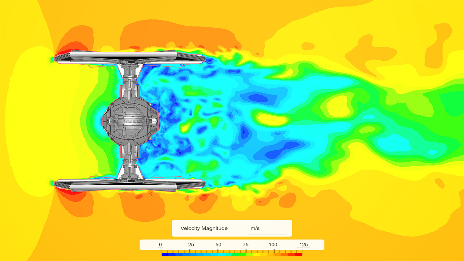
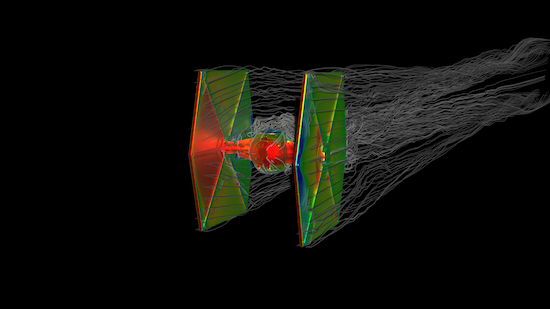
SimScale CFD simulation on the TIE Fighter showing velocity. Image courtesy of SimScale.

Latest News
September 29, 2022
Anybody with a basic understanding of aerodynamics could immediately see the design flaws in the TIE Fighter, the iconic battlecraft for the Imperial Fleet in the “Star Wars” universe. It has no wings to create lift.
Instead, it has vertical solar panels, perhaps useful for docking but not helpful for taking off or landing. The fuselage is a near-perfect sphere. A spinning ball, like a musket shot from a gun, is quite efficient in flight, but, for the sake of the pilot inside, the TIE Fighter’s hull cannot spin.
For its movement and speed, the vehicle seems to be relying primarily on the thrust from its twin ion engines. Our instincts are likely to tell us that in the real world, it might have a difficult time lifting off, let alone staying airborne. So DE enlisted the help of some computational fluid dynamics (CFD) experts to fact-check it. We also invited them to give their own ideas on how they might redesign it for aerodynamics. The resulting conversations shed light on how aerospace engineers think.
Pre-Simulation Judgments
Most publicly available 3D models of the TIE Fighter are made for rendering, with some showing more details than others. Since it’s a spacecraft that doesn’t exist in the real world, finding a detailed CAD model is out of the question. So a high-quality mesh model from a 3D content site is the best we can hope for.
“I’m not too concerned about how clean or closed the model is,” says Nolan Halliday, senior application engineer, SimScale. “We have the technology to deal with nonmanifold surfaces, or those that are not stitched together or poking into each other.” He explained this capability in SimScale was made possible by the Pacefish LBM solver from Numeric Systems GmbH, a SimScale software partner.
Imperfect CAD geometry is a problem engineers routinely encounter when they get a CAD model for a real project, he explains. “When we get an automotive CAD model, it’s not always clean or perfect. That’s why most modern CFD packages have tools to deal with it,” he said.
For the boundary conditions, Halliday assumed the craft was operating in an earth-like atmosphere. “There’s enough lore and literature on the ‘Star Wars’ universe and its technology that I could easily get the parameters,” he says. Indeed, anyone who wants to find the top speed and the dimensions of the TIE Fighter only needs to Google it. Wookieepedia—the Star Wars Wikipedia—gives you all that you need to know.
Apolo Vanderberg, Autodesk business consultant and additive manufacturing (AM) specialist, chose overengineering to account for the unknown.
“We know about the conditions on earth and we have a pretty good idea about the other planets in our solar system. So if it can handle conditions 10 times worse than the earth, then we can assume it can handle anything less,” he reasons.
Using Autodesk Fusion 360’s generative design tools, Vanderberg wanted to explore other topology options—in particular, the arms connecting the cockpit to the solar panels. Even if air resistance isn’t a problem in space, “you still have to deal with acceleration, which is affected by mass. So lightweighting the topology is a good idea,” he notes.
The TIE Fighter’s maximum speed is 4,000G, per Wookieepedia. “So we could set the factor of safety to, say, 10,000G, and find out what would happen to these structures in flight,” Vanderberg says.
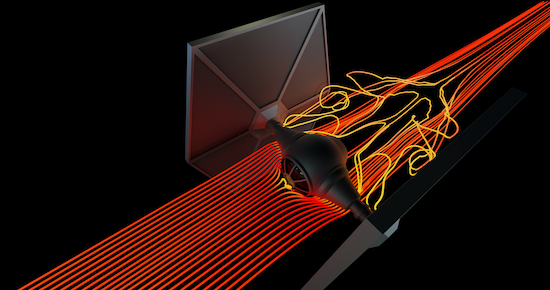
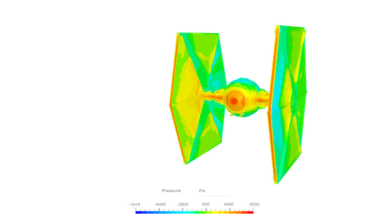
He predicted the spherical fuselage would produce drag behind it. “It would create a low-pressure region behind it, which creates drag,” he says. He believes the tried-and-true teardrop shape, like the nose of a concord or supersonic plane, would be better.
Will It Fly?
The answer is, yes, but barely. Halliday ran a transient simulation, showing several seconds of the TIE Fighter in instantaneous velocity.
“In any atmosphere similar to the earth, the pilot is in for a terrible time,” says Halliday. “It has too much drag and little to no lift, so its propulsion system needs a lot of thrust.” Aerodynamic control would also be a huge issue, relying solely on the main engines or thrusters for maneuvering.
Based on the craft’s movements he has seen in movies, Halliday chose to simulate it at 100 meters per second. The surrounding air volume was broken up into 30-40 million cells. The job was completed on SimScale’s Lattice-Boltzmann solver with graphics processing unit (GPU) acceleration.
“These types of jobs used to take days, but now, it only takes a few hours,” Halliday says.
The result confirmed much of what he suspected, but also yielded new insights. The surface of the solar panels and the fuselage have too many exposed mechanical features, creating turbulent flows, he says. “This is not what you want to see in your leading edges,” Halliday says. “If they could be covered under a smooth skin, like airplane wings, it would be a lot better.”
There’s another disadvantage with the fighter’s side panels. “At yaw, when it’s turning, the drag coefficient will skyrocket, because you are essentially putting a flat surface directly into the wind’s path,” Halliday says.
Halliday didn’t conduct a stress analysis, but he guessed the stress on the panels would be significant. “If we know the materials it’s made of, it will tell us if it can withstand the stresses at yaw,” he says.
(Editor’s note: I had no way to contact the Imperial Army’s engineering division to obtain the fighter’s material information, so I left it alone.)
Ideas for Redesign
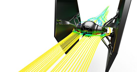
Christina Peristeri, a CFD engineer at Ansys, used a high-quality model found on TurboSquid by JTheMaker. No geometry preparation was required because she used the fault-tolerant meshing workflow in Ansys Fluent, which creates a wrap around the model. She applied polyhedral and hexahedral meshes, generally considered most efficient in keeping the mesh-count low while giving accurate results.
Following some publicly available specs, she simulated the TIE Fighter at 200 meters per second. She ran a transient simulation in the cloud using four NVIDIA A100 GPUs with the new Live-GX native GPU solver in Ansys Fluent. Meshing took 57 minutes; the simulation took three hours.
“I would get rid of the sphere and go with a teardrop-shaped body, like a traditional cockpit. That gives you better drag coefficient numbers,” Peristeri says. With a sphere, the drag coefficient was 0.47. By changing the cockpit from a sphere to a teardrop shape, the coefficient dropped to 0.04—quite a difference.
“The leading edges on the solar panels should also be smoother and more streamlined, like the aerodynamic surfaces on race cars, and the panels should be placed horizontally,” she adds. “I would add some adjustable vortex generators to keep the airflow attached to the surface when the TIE fighter flies at different pitch angles.” Similarly, Halliday of SimScale also suggested adding some airfoils and fairings, along with cambered wings.
All participants in this article used cloud-hosted simulation tools to complete their tasks, with good reason.
“On a desktop, you would have to run the simulation sequentially, but in the cloud, I could simulate the TIE Fighter at three different speeds, maybe in three different atmospheric conditions,” Autodesk’s Vanderberg says. “CFD works well with GPUs so we could run high-resolution transient simulations like these at a very low cost,” adds Halliday.
With Autodesk Fusion 360’s generative design, Vanderberg identified a spider-leg structure that strengthened the cockpit’s connection to the solar panels. He compared CFD results from before and after the redesign.
“By running a quick generative design study, we start to immediately see how we can reduce the mass required to connect the existing solar panels while also leveraging those structures to generate lift. Our quick test shows how different structures could be used and the impact these changes would have on flow characteristics. Structures like this can also simplify construction through part consolidation, which would enable the Empire to increase efficiencies on its production line and potentially reduce waste, making the TIE Fighter a more sustainable vehicle,” he says.
If the TIE Fighter’s only purpose is dogfights in space, very few of these concerns above would apply, but in any earth-like planet, the current design “is like throwing a rock into the air,” Halliday says.
Kenneth Wong is DE’s resident blogger and senior editor. Email him at [email protected] or share your thoughts on this article at digitaleng.news/facebook.
More Ansys Coverage
More Autodesk Coverage
More SimScale Coverage

Subscribe to our FREE magazine, FREE email newsletters or both!
Latest News
About the Author
Kenneth Wong is Digital Engineering’s resident blogger and senior editor. Email him at [email protected] or share your thoughts on this article at digitaleng.news/facebook.
Follow DERelated Topics


