Integrate FEA and CAD
There are several obstacles that act as roadblocks to the successful integration of finite element analysis with CAD. Let's take a look at what they are and how to avoid them.


Latest News
September 1, 2013
For much of engineering product development, it is a CAD-centric world. That’s great if you are a CAD driver, but spare a thought for the manufacturing and analysis side. Getting that CAD model into a format that’s ready for delivery to a numerically controlled machining program or a finite element analysis (FEA) solver can be really tough.
 An ideal FEA process and data flow. |
While technology has evolved tremendously over the past 40 years (see “A Brief History of CAD-to-FEA Data Transfer” below), there are still trouble spots. This begs the question: If the current state of the art is mature enough to allow a high level of compatibility between geometry and meshing, why can’t we seamlessly integrate CAD with FEA?
I have covered adequacy of CAD geometry for FEA in previous DE articles on meshing (January 2013) and idealization (April 2013). We can break down four areas that may be problematic as follows.
1. Geometry
There are several issues affecting the preparation of an FE model that are simply due to the definition of geometry coming from CAD. These are generally well understood, but represent a burden for the analyst. Small slivers and tolerance errors result in cracks or negative volumes in the geometry as perceived by the mesher. Unwanted features such as tooling holes, and unwanted parts such as handles, sealing rings, etc., need to be removed.
Specialist software provides geometry cleanup and de-featuring—and the technology is migrating to the general-purpose preprocessor. However, it is never foolproof and the geometry still has to be carefully reviewed.
The job of segregating out unwanted parts can be a major task. A piping installation analysis I did several years ago had a part count of more than 5,000. There was no way to automatically identify how each instance of solid geometry related to a physical part. It took many man-hours to reassemble and idealize in the preprocessor, and reduce to 200 structural parts.
2. Configuration
The CAD model defines the product in a specific configuration. So, for example, bearings are concentric within housings. Structural analysis may require the bearing hard up against its mating surface under a particular loading. This means changing the configuration. Other examples include crane arms, suspension fittings, control services, etc.—each of which will be drawn at datum positions, but will need analyzing in operating configurations. It can take trial and error to find critical configurations.
3. Robustness
CAD geometry robustness may be poor because of the interdependence of geometric features. For example, removing a hole or fillet may invalidate the CAD model. To some extent, this can be aided by improving the hierarchy, but that is a tough thing to do as a design is evolving.
One major CAD breakthrough here is synchronous technology, whereby a hierarchical interdependence can be transformed to a simpler parametric definition. Some preprocessing technology helps by allowing the import of dumb geometry and subsequent intelligent parameterizing. The danger here, however, is that design intent may be lost.
4. Idealization Method
This is probably the biggest roadblock to automated CAD and FEA integration. Some structures, described as “potato-like” in appearance, require minimum de-featuring and allow rapid meshing with 3D elements. If the real-world loading and constraint conditions can be matched, we have an adequate representation of the structure.
At the other extreme, thin-shell fabricated structures such as aircraft, ships, buildings and pressure vessels may be difficult to work with. My current FEA project does not use any original CAD geometry solids or surfaces, for example. The general approach is to clone and adapt surfaces, and slice with keyline geometry to suit the 2D element idealization.
Breaking through the Roadblocks
The key to successful integration between CAD and FE in these cases is to use “FEA-friendly CAD.” In a manual approach, the analyst and designer work together to identify features and parts to be eliminated and cleaned up in a variant of the CAD model intended for FEA. The level of idealization, from minimal in largely solid-type structures to extensive in fabricated thin-shell structures, is the main driver.
I have seen this implemented very successfully in some companies. But in other companies, cultural, geographical, union or other factors prevent the approach—and management misses a fundamental opportunity to increase productivity.
The software industry still strives to make integration happen automatically. Gazing into a crystal ball, I imagine sitting down with the designer in front of CAD/FEA-integrated software that would allow us to guide the geometry manipulation and subsequent meshing. We would agree on the level of idealization and what key geometry should be tagged to represent the structure efficiently and accurately. We may end up with skeleton geometry that sketches the structural representation. Association of materials, properties and loads and boundary conditions should be highly interactive. The software would then stitch this up and carry out the meshing.
When Do We Do the Data Transfer?
We’re trying to push simulation as high up the design chain as possible, so that it can really have an impact on the product. Often, FEA occurs after all design is complete and is part of the sign-off process. This can cost time and money if redesign is needed, and can make FEA appear as a roadblock.
The CAD-to-FEA integration needs to be a lot smarter to achieve this. It is not just about file formats and geometry transfer. It is about the way people collaborate on creating an engineering product. It is not even just about the tools, such as product lifecycle management (PLM), simulation data management (SDM), etc. It is about creating the culture that enables and encourages the transfer of maturing design intent and structural integrity through the conceptual phase to the final product definition.
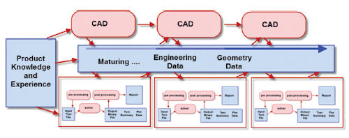
The diagram on page 48 shows an evolution from today’s typical process flow. We want any product knowledge and experience to be used early in the design evolution to influence both CAD and FEA, as shown by the links in the figure. On the FEA side, the key is having a modeling paradigm that can adapt quickly to changes, and offer as feedback useful structural information to the design process. Changes include configuration, materials and loading environment, and are bound to occur as the design matures.
We have a sequence of FEA tasks now. Each may represent very different approaches, such as initially a simple 1D beam representation maturing through to a full solid model. Or each may be modifications to a common model, evolving through the design phases. Current collaborative screen-based tools allow sharing of model descriptions and design intent, and this will streamline the process. However, what is less clear is how actual geometry data can be meaningfully transferred between the CAD and FEA functions.
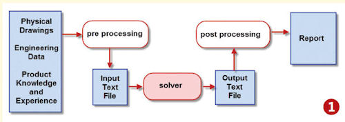
| A Brief History of CAD-to-FEA Data Transfer I started doing serious finite element analysis (FEA) in the mid-1970s. CAD had not been thought of yet. I remember my skepticism when I was first shown remote text terminals linked to the mighty IBM mainframe! Drawings were produced the old-fashioned way: on drawing boards. Constructing a mesh required overlaying tracing paper onto the drawing, and penciling in nodes and elements. This was extremely tedious and error-prone. Luckily, most structures were thin skin components that could use 2D element meshing. I built some meshes to carry out damage tolerance analysis on 3D lugs, which predated the Rubik’s Cube in spatial complexity. Fig. 1 shows the typical workflow from that era. The only computer program shown is the FE solver. The pre- and post-processing required a written text input file converted to punch card format and fan-fold paper text output. The figure indicates knowledge and experience of the product, as well as other engineering data, such as material properties, load cases, fabrication techniques, etc.
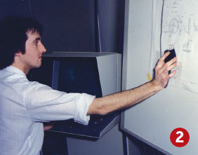
When thinking about CAD-to-FEA integration today, the same importance must be placed on this information as well as the geometry definition. The end result is still familiar today—the required reporting level to support sign-off, design review or whatever the objective of the analysis is. The Eighties Revolution Fig. 2 shows one revolution of the early 1980s, the digitizing tablet. The drawing is pinned to a special board that has a mesh of fine resolution wires able to detect mouse location. Clicking creates nodal points in the preprocessor as a starting point for the meshing.
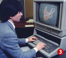
As CAD came on-stream, geometry data formats were developed to allow file transfer of data between CAD and the FEA pre-processor. Typical formats were STEP and IGES. Data transfer success was hit and miss; it was dependent on the compatibility of the geometry mathematics and tolerances in the CAD and FEA pre-processors. I first came across solid modeling technology in the mid-1980s, with very early incarnations of GEOMOD, CATIA and the like. Fig. 3 shows a missile-packaging project we were very proud of—the date on the screen is February 1984! This technology has developed tremendously since those early days, with corresponding improvement in the mathematical sophistication and completeness of the geometry definition. It is now expected that the data interchange between a CAD program and an FEA preprocessor will be good. The tightest linking is between embedded FEA solutions within a CAD program.
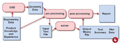
The State of the Art Fig. 4 shows a typical setup today. The pre- and post-processing are enabled with meshing and results visualization tools. Many CAE solutions now include all three elements within a single, or closely linked products. The input text file to the solver still remains in the vast majority of cases. It is often relegated to a background role, but it’s in such a definitive and robust format that it defies evolution. Conversely, output format continues to evolve, driven by the data storage and retrieval requirements of today’s large models.
Fig. 4 also adds CAD into the process, with technically tight data exchange with the FEA pre-processor. The designer and analyst still both need to refer back to the broader range of product data, and the knowledge and experience surrounding that. —T.A. |
Closer, But Not There Yet
We have come a long way since the 1970s and ’80s; however, it is still frustrating that the long-held dream of FEA-to-CAD integration has not been fulfilled. Some will point (quite rightly) to specific, highly successful, integrated processes that underpin significant company success. However, in my experience, each of these represents a focused investment in customized solutions. As such, they are a testament to the vision and innovation of the engineers and management involved.
I think that sums up where we are: You can make CAD-to-FEA integration work very successfully in your company. Having a standardized product line helps. But in general, with the current level of technology that is available, you are going to need a clear vision, skill and ingenuity to develop your process.
Tony Abbey is a consultant analyst with his own company, FETraining. He also works as training manager for NAFEMS, responsible for developing and implementing training classes, including a wide range of e-learning classes. Send e-mail about this article to [email protected].
More Info
Subscribe to our FREE magazine, FREE email newsletters or both!
Latest News
About the Author
Tony Abbey is a consultant analyst with his own company, FETraining. He also works as training manager for NAFEMS, responsible for developing and implementing training classes, including e-learning classes. Send e-mail about this article to [email protected].
Follow DE

