
With STAR-CCM+, engineers at Owens Corning could predict behavior of tricky welding areas and apply the correct amount of heat. Image courtesy of CD-adapco.

Latest News
October 1, 2015
By John Kirkley, CD-adapco
It wasn’t your everyday assignment. Byron Bemis, senior research associate at Owens Corning, and his team were asked to design a new generation of manufacturing components that could not be made using existing manufacturing processes. Owens Corning is a leading global producer of residential and commercial building materials, including insulation and roofing shingles; glass-fiber reinforcements for products such as cars, boats, wind blades and smartphones; and engineered materials for composite systems. Its Science and Technology Center, where Bemis is located and much of the company’s research and development (R&D) takes place, is located in Granville, OH.
With this particular R&D project, Bemis and crew were breaking new ground. To design and fabricate the requested parts, their initial designs called for blind keyhole welding through one sheet metal part and into another. “Developing the welding parameters to make those welds work reliably and robustly took a lot of trial and error,” Bemis says. “To accomplish this using physical prototypes meant fabricating the individual component parts and then laser welding them up using a set of pre-determined parameters to see what happens. You continue doing simulation of laser welding shortens design cycle and optimizes component design at Owens Corning this until you find the right combination.”
Bemis adds that one of the most challenging aspects of this project was the necessity to weld close to small features or near corners or edges. If the laser is running too hot or moving too slowly, the feature or edge could melt, ruining the part.
These were small welds, varying in size from millimeter to submillimeter scale, made on very small parts that demanded high-precision fabrication. Bemis says they were running very narrow weld beams — in many cases 50-micron weld spots using up to a kilowatt of laser power on an individual spot.
The materials used were alloys with very high melting points, high molten metal viscosity and surface tension. This made for some interesting, non-standard welding physics.
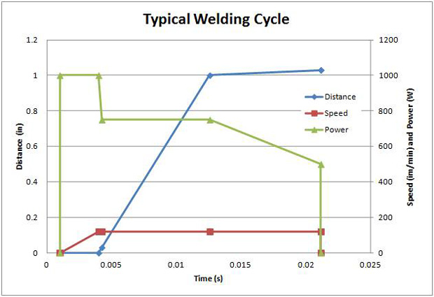 Shown here, the typical weld cycle requires varying levels of heat and distance. With simulation, engineers can run different scenarios and see how the metal reacts. Image courtesy of CD-adapco.
Complex geometries were also involved, including small features, edges and circular sections. Because deep penetration was necessary to make the part, a keyhole mode was required. Keyhole mode is a welding technique in which a concentrated heat source, such as a laser, penetrates completely through a work-piece, forming a hole at the leading edge of the molten weld metal. As the heat source progresses, the molten metal fills in behind the hold to form the weldbead.
All of these considerations — in particular, the blind keyhole welding — meant a lot of trial and error. Running hundreds of repeated physical experiments using expensive alloys and high-value component parts was prohibitively expensive and time consuming. It was obvious that simulation was the answer. But high-fidelity simulation of the complete keyhole physics was very complex, expensive and slow. The simulation had to adequately predict quantities of interest — such as weld pool diameter and zone shape as well as penetration depth — to specify the optimal laser process parameters.
Seeking a Solution
Contemplating the task at hand, Bemis recalls, “We needed an economical solution — one that was fast, robust and easy to use.” In search of this solution, he spoke with his support engineer at CD-adapco, who had experience in simulating welding. Based on the guidance from CD-adapco he decided to use STAR-CCM+ to conduct the simulations.
STAR-CCM+ features a comprehensive suite of geometry creation and preparation tools that significantly reduce the number of hours required to prepare a model for meshing. In addition, STAR-CCM+ features a single integrated environment, which provides a fast, most automatic route from complex CAD models to engineering solution. This met two of Bemis’ main criteria: speed and robustness. As to ease of use, the software’s powerful meshing tools cut down geometry preparation and meshing time from weeks and months to hours, while delivering a high-quality mesh on sophisticated geometries. All of these capabilities can be leveraged from within familiar CAD and PLM (product lifecycle management) environments.
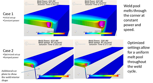 With STAR-CCM+, engineers at Owens Corning could predict behavior of tricky welding areas and apply the correct amount of heat. Image courtesy of CD-adapco.
Bemis used STAR-CCM+ to simulate the welding heat transfer process. The solution proved to be excellent in predicting both the weld width and the behavior of features affected by the blind welding. “STAR-CCM+ has the unique ability to simulate the welding process and provide insight into the thermal transient experienced during welding in a manner that is both practical and fast enough for industrial use,” Bemis says.
Power of Overset Meshing
For the past 30 years, engineers trying to perform computational fluid dynamics (CFD) simulations struggled with the interaction between multiple moving objects. Traditionally, this required the generation of an interconnected mesh between the objects, an intensive manual process that was extremely difficult and time consuming. In fact, it was almost impossible if extreme ranges of motion or close interaction between objects was involved.
With Overset Mesh, STAR-CCM+ solved the problem. Overset meshing — sometimes called “overlapping” or “chimera” mesh — in STAR-CCM+ presents a new and more effective way to handle the modeling and simulation of the complex physics associated with moving objects. This approach allows the user to generate an individual mesh around each moving object, which can then be moved at will over a background mesh.
“In the welding process, you can either move the heat source or the material,” Bemis says. “Overset meshing allows you to simulate the relative motion between the heat source and the parts that are being welded together. That motion, along with the laser’s power, really dictates how wide the weld gets, the size of the molten zone and the depth of penetration,” Bemis says. “With the use of overset meshes, we were able to run a fairly coarse background mesh as well as a fine, detailed mesh of the weld zone. We moved rather arbitrarily through the background mesh and generated any weld pattern we wanted. Some of the welds were 100 mm long and 0.5 mm thick, resulting in big aspect ratios and a really large mesh count to refine the simulation in the weld zone areas.”
Bemis was working with a moving target. Heat tends to build up in the weld zones resulting in changing parameters as you move from weld to weld. Overset meshing allows the designer to simulate individual welds on the component, taking into consideration the changing nature of the material being worked on due to heat transfer. An implicit unsteady simulation with a moving overset mesh permits the prediction of the extent of the molten zone as it progresses along the joint, temperatures in the work piece, and heat transfer to the fixture. Parameters such as laser power, travel speed, acceleration, and pulse frequency can be tuned to provide the desired optimal weld.
A New Methodology
The research team also worked with a methodology recently introduced by CD-adapco known as Multidisciplinary Design eXploration (MDX). MDX allows the automatic testing of designs from early in the concept stage against all of the physics that might impact performance. This is possible because the increasing capabilities of sophisticated simulation software such as STAR-CCM+ allows engineers to determine how a product will perform under the actual conditions it will face during its lifecycle.
“We used Optimate to explore the parameter space up front and alter the process and components to get the final results we wanted,” Bemis says. “We were able to set up weld speed, power, and field functions to mimic laser control. We could ramp the laser up and down, simulate voltage feeds, and all the other parameters that Optimate could access. We then used the software to run cases to determine such things as how far back from a corner we needed to slow down, and how much to drop laser power in order to make a weld around a sharp corner while maintaining the same heat effective zone in the base material components. The simulation allowed us to prescribe all the welding parameters for experimental validation early in the design process.”
“Accurate Enough”
He points out that using the CD-adapco simulation solutions meant that the results were “accurate enough.” Rather than attempting to generate a perfect simulation of the problem, the results they obtained provided sufficient information to accurately predict real world weld characteristics, evaluate parameters and decide which directions to take.
This process, Bemis says, was very fast considering it was a fully transient simulation with motion and overset meshing. He was able to run enough cases on a high-end workstation loaded with STAR-CCM+/Optimate to allow design space experimentation and optimization. The software is flexible enough to simulate complex motion in time-dependent parameters for heat input field function interface. “It’s incredible to have that kind of power at your fingertips without having to write your own C code or FORTRAN,” Bemis says. “I figure we saved at least six months of trial and error development — six months of experimental lab time — which is huge. In fact, by freeing up more time for design, we managed to figure out how to avoid using blind welds, a definite plus. “The high quality simulation using STAR-CCM+ and Optimate allowed us to explore the research, design and analysis of the component as well as the manufacturing process all at the same time. We were able to deliver the final component design to our manufacturing facility complete with all the fab steps and processes in place. This is a very powerful way to work.”
“We use STAR-CCM+ every day,” Bemis says. “The CD-adapco software has become an integral part of our design and development activities.”
More Info:
Subscribe to our FREE magazine, FREE email newsletters or both!
Latest News


