

October 1, 2005
By Fred Arnold and Murali Pandheeradi
Welding is a fundamental manufacturing technique used to join metal components. While a variety of welding processes exist, most involve the application of heat to induce coalescence of the metal in the adjoining parts. The simulation uses a sequentially coupled approach in which a thermal analysis is followed by a stress analysis. The temperature results from the thermal analysis are read into the stress analysis as loading to calculate the thermal stress effects. The thermal analysis makes use of ABAQUS user subroutines DFLUX, GAPCON, and FILM. The objective of the simulation is to predict post-weld deformation and residual stress distribution.
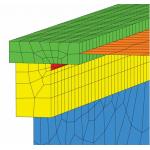
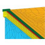
The model is constructed using solid and shell elements. A solid representation is used in the weld area to ensure more accurate capture of the high solution gradients. Regions outside the weld zone, where thermal gradients are not as severe, are modeled with shell elements to reduce the overall model size. The transition between the shell and solid regions is achieved using tied contact for the thermal analysis and shell-to-solid coupling for the stress analysis. The mesh is shown in Figure 1 (left). The weld bead is shown in red. Thermal Analysis Procedure The thermal analysis is performed to calculate the heat transfer resulting from the thermal load of the moving torch. Three user subroutines are activated for the thermal analysis: The structural analysis uses the thermal analysis (temperature) results as the loading. The objective of the structural analysis is to determine the stresses and strains induced in the weld region during the cooling transient. Boundary conditions are applied to restrain the system against rigid body motion.
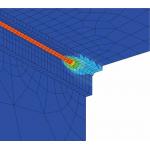
Results and Conclusion Typical thermal results are shown in Figure 2 (left), which displays a contour of nodal temperature as the torch travels along the weld line.
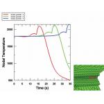
In addition, as the torch passes the same weld line point, conductive and convective heat transfer is activated, causing a rapid drop in temperature as thermal energy is transferred to the surrounding structure and environment. Figure 3 (right) shows the 35 s transient temperature profile at three points close to the start of the torch path. The peak temperature is reached when the torch is activated. A sharp temperature drop is observed after the torch passes.
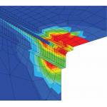
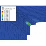
The stress response of the structure is driven by the high thermal gradients. Figure 4 (left) and Figure 5 (below), respectively, show plots of the von Mises stress and the effective plastic strain approximately 35 s into the process.
In conclusion, ABAQUS/Standard provides a set of general, flexible modeling tools that allow for the prediction of residual stresses and final shapes in welded components. Fred Arnold and Murali Pandheeradi are Senior Application Engineers for ABAQUS Erie. They consult with ABAQUS users regularly on the use of ABAQUS to model welding processes. Send your comments and thoughts about this article through e-mail by clicking here. Please reference Welding, “EoA November 2005” in your message. | |||||||||||
Subscribe to our FREE magazine, FREE email newsletters or both!
About the Author
DE’s editors contribute news and new product announcements to Digital Engineering.
Press releases may be sent to them via [email protected].


