Moldex3D Helps Synventive to Simulate Advanced Pin Movement

Fig. 3: Uncontrolled melt front advancements are produced in original sequential valve pin movement setting.


Latest News
February 1, 2018
Executive Summary
Sequential valve gating is a common practice that allows molders to manufacture large injection molded parts with high quality surface finishes. However, this creates defects such as pressure flow marks on unpainted parts, reflection marks on painted parts and hot spot marks opposite of direct gated nozzles (Fig. 1). Synventive Molding Solutions manufactures hot runner systems for the plastics injection molding industry.
Its activeGate Technologies are a line of control systems that give molders using valve gated hot runner systems control beyond the on/off ability of conventional valve gates. The molder can control the stroke, velocity and acceleration of the valve pins. Moldex3D is able to simulate this high-level control and allows molders to better predict and prevent common defects in injection-molded parts.
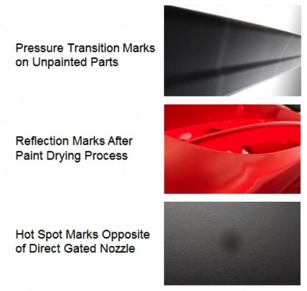 Fig. 1: Common molding defects on standard sequential valve gating system. Image courtesy of Moldex3D.
Challenges
- Common molding defects for injection molded parts by sequential valve gating system.
- To eliminate defects without rebuilding a mold or retrofitting an existing mold for testing.
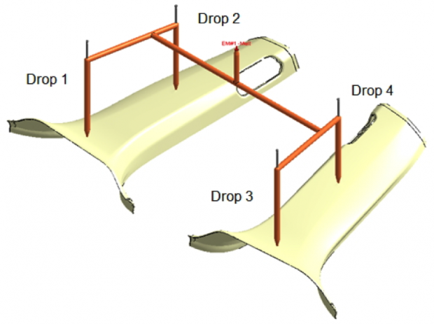 Fig. 2: Hot runner layout design. Image courtesy of Moldex3D.
Solutions
Moldex3D Advanced was utilized not only to model the system with standard sequential valve gating system to identify the molding defects but also to simulate valve pin movement control to optimize the process (controlled sequential valve gating system) and eliminate the defects found in the injection molded parts.
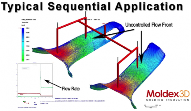 Fig. 3: Uncontrolled melt front advancements are produced in original sequential valve pin movement setting. Image courtesy of Moldex3D.
Benefits
- early detection of common defects in injection-molded parts;
- successfully identified defects that can be eliminated with activeGate controls through pin movement simulation; and
- saved time and money by scrapping less parts.
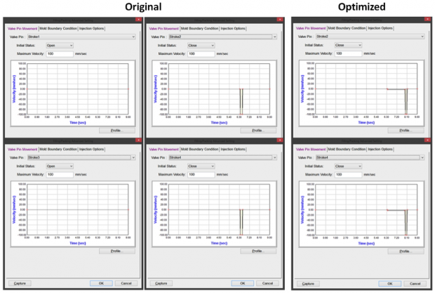 Fig. 4: Fast and slow opening speeds between original and optimized sequential valve pin movement settings. Image courtesy of Moldex3D.
Case Study
The objectives of this project are to accurately identify the common molding defects in sequentially molded parts, to prepare a simulation that shows an area that has high potential of creating those defects, and to simulate the use of valve pin movement technology (controlled sequential valve gating system) called activeGate Technologies, as the solution to resolve the defects.
The whole model itself is a two-cavity mold that utilizes a two valve-gated hot runner system for each cavity (Fig. 2). The second set of valve pins (Drop 2 and 4) is opened at full speed after the melt front from the first set of valve pins (Drop 1 and 3) passes Drop 2 and 4. When Drop 2 and 4 opened, the material inside, which has been compressed under high pressure, is released into the cavity.
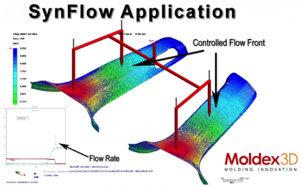 Fig. 5: Controlled melt front advancements occur after adopting optimized sequential valve pin movement setting. Image courtesy of Moldex3D.
At this point, a few things were detected. One, the melt front is pushed forward at a much faster rate than the first nozzle. This shows up as a large melt front advancement, which can be seen from large distances between iso-contour lines, and it can lead to pressure transition marks. Two, some material can flow backwards and create dense areas, which can be seen from small distances between iso-contour lines. These two indicate large uncontrolled melt front advancements and melt front stagnation on the side of parts (Fig. 3). When the parts come out, they may still look acceptable, but if we paint these parts and then put them in a dryer, the dense areas will try to relax and generate reflection marks. Also, the material that was deposited on the wall can be re-melted by the high-pressure melt that later enters the cavity, resulting in a hot spot mark.
The change made was to control the opening speed and acceleration of the valve pin in the second nozzle. The second valve pin (the valve pin represents both Drop 2 and 4 in the valve pin movement setting) is not opened at full speed anymore but at controlled speed at 6.35 s (Fig. 4). This creates a small gap which allows the pressure in the second nozzle to equalize to the system. With an equal pressure, the material will not advance the melt front too much from the second nozzle, push material backwards to create the dense areas, or re-melt the material opposite of the gate. The simulation result shows that the iso-contour lines look uniform throughout the entire part (Fig. 5).
Three injection-molded products were produced using the controlled sequential valve gating system (the pin was opened slowly to control the release of plastics into the cavity) for the verification that the controlled process could improve the standard/conventional process. The three products were seat back, glove box, and door panel. The results show that the defects that occur under standard/conventional process can be eliminated (Fig. 6).
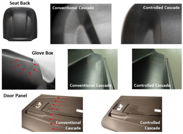 Fig. 6: The validation results show that the controlled process can effectively eliminate defects in injection-molded parts. Image courtesy of Moldex3D.
Result
With Moldex3D, Synventive succeeded in identifying the injection-molded parts that could potentially have defects under standard valve pin movement setting. Equally important, Moldex3D could simulate the advanced valve pin movement control that helped to alter the characteristics of the melt front and eventually eliminate any defects that might have occurred. In addition, the molders could save time and money by scrapping fewer parts from the optimized sequential valve pin movement setting.
Subscribe to our FREE magazine, FREE email newsletters or both!
Latest News


