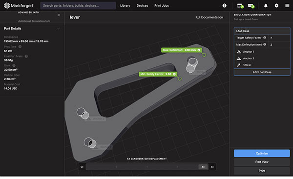
Simulation results in Markforged’s slicing platform, Eiger, showing a user how stiff and how strong the part is. Image courtesy of Markforged.

April 19, 2023
Multimaterial assemblies are the norm in product design, but in 3D printing, such assemblies required technological breakthroughs. While assembling discrete parts with different properties (for example, rubber and metal) demanded no special process, printing rubber-like materials and brittle materials from the same machine was a quandary. The operative word to note here—was—but not any longer. Today, many hardware makers offer printers with multimaterial printing capability.
The Fab@Home printer, released in 2006, was an early model with multimaterial printing. The printer was the outcome of a student-led project at Cornell University’s Mechanical & Aerospace Engineering Department. The project also set precedence as an example of open-source 3D printer development.
As open-source hardware, the printer’s design is public domain, which allows others to replicate it. It’s part of the do-it-yourself printer movement. The printer uses a multiple syringe-based deposition method to accomplish multimaterial printing.
One example of a commercially available multimaterial printer is the Projet MJP 5600 from 3D Systems.
“The system’s multimaterial capabilities enable customers to digitally blend rigid and elastomeric materials at the voxel level to achieve superior mechanical properties for a wide range of applications, including assemblies, rubber-like components, jigs, and fixtures, and dies,” the company notes. “Coupled with 3D Sprint software, the ProJet MJP 5600 also allows customers to assign different material blends to separate shells within a single part.”
Another example is the Stratasys J750, which is part of the Objet Connex multicolor, multimaterial 3D printer series.
“This new solution enables customers—for the first time—to mix-and-match full-color gradients alongside a wide range of materials to achieve one-stop realism without post-processing,” Stratasys writes.
Though multimaterial printing is no longer a hurdle, simulating such print jobs remains a challenge. We spoke to Markforged, which developed the first multimaterial continuous carbon-fiber printer, to understand the possibilities—and the limits.
Defining Multimaterial
The term multimaterial should be closely examined. It can mean different things for different people.
“For some, it means printing with a filament made of two different materials, like a nylon base material filled with microscopic, chopped fibers,” Rick Dalgarno, product marketing manager, Markforged, says. “So at the micro level, the filament itself is multimaterial. For others, it means printing in rubber-like materials as well as solid materials. In our case, we have our base material Onyx, which has different properties than our continuous fiber materials. So we can print in two distinct materials.”
“With fused filament fabrication (FFF), also known as fused deposition modeling (FDM), the wall thickness can be adjusted and the infill density and pattern can also be adjusted, resulting in parts that have different properties in different regions,” Dalgarno says. “The ability to print with two distinct types of materials will also produce a part that exhibits different mechanical properties in different regions. This is an important feature for healthcare or medical usage, where the printed object needs to mimic a mix of soft tissues and bone-like structures.
Assessing Multimaterial Part Performance
In April 2022, Markforged acquired Teton Simulation, a cloud-based simulation software maker. With this acquisition, Markforged gained Teton’s SmartSlice technology.
In the acquisition announcement, Markforged states, “Markforged will integrate Teton’s technology with its 3D printing software solution, Eiger, as a subscription add-on … The acquisition adds strategic functionality to the Digital Forge to give Markforged’s thousands of users confidence that printed parts will perform as intended, enabling them to replace even more end-use metal parts with validated continuous fiber reinforcement (CFR).”
Eiger software includes an advanced feature, called Blacksmith, described as “autopilot for digital manufacturing, connecting part design, production, inspection and quality control.”
“Blacksmith is basically in-process part inspection,” Dalgarno says. “It scans your part as it’s being printed, using a laser micrometer that is built into the printer, and allows users to measure and inspect the printed part within Eiger.”
He notes the company also offers various management and integration features for organizations with a distributed fleet of printers or users in different locations.
The simulation feature from Teton has been integrated into Markforged’s Eiger software and was to be available as a free trial through April 1. It will soon be offered as part of a paid subscription, according to Dalgarno.
Simulation and Slicing
Markforged’s simulation technology is integrated into Eiger, its slicing program, Dalgarno points out. Eiger reads CAD files as STL. A hurdle with simulating the performance of printed parts is the material data. Take, for example, thermoplastic polyurethane (TPU).
“We do print TPU, which is a flexible material. In theory, we could simulate parts that have TPU and other materials in them. At the moment, we haven’t characterized TPU so we don’t simulate parts printed with TPU. As time goes on, we’ll quantify more materials for our simulation technology,” says Dalgarno.
When material data for a given material is not readily available, it has to be tested first to ascertain its mechanical properties. “It means we need to print some dog bone-shaped parts with different raster angles and orientations and test them to get the mechanical properties, such as stiffness and strength. And that feeds into our simulation software, which is powered by a finite element analysis (FEA) engine,” says Dalgarno.
Markforged’s software is developed specifically for parts made with FFF, also known as FDM.
“Different variables affect the 3D-printed parts and how they perform. They include how you orient the part on the print bed, the print settings, how thick the shell is, what the infill density is, whether you’re using continuous fiber on the inside and so on. Traditional FEA simulation tools are not well equipped to simulate 3D-printed parts because of the internal complexity of those parts,” says Dalgarno.
Markforged has an existing partnership with Hexagon. An important component of the partnership is the ability to simulate Markforged parts in Hexagon’s Digimat software.
Announcing the partnership in 2019, the two companies wrote, “Customers can already implement material analysis for the Markforged continuous carbon fiber and Onyx materials within MSC’s Digimat materials modeling software, and the cooperation will soon extend to provide full-process simulation and part performance with FEA within a common CAE environment.”
More 3D Systems Coverage
More Markforged Coverage
More Stratasys Coverage
Subscribe to our FREE magazine, FREE email newsletters or both!
About the Author
Kenneth Wong is Digital Engineering’s resident blogger and senior editor. Email him at [email protected] or share your thoughts on this article at digitaleng.news/facebook.
Follow DE

