
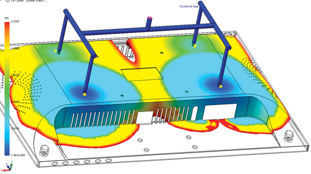
SOLIDWORKS Plastics, part of the company’s simulation software lineup, givers SOLIDWORKS users the ability to simulate and analyze mold filling. Image courtesy of SOLIDWORKS.


Latest News
June 1, 2016
 SOLIDWORKS Plastics, part of the company’s simulation software lineup, givers SOLIDWORKS users the ability to simulate and analyze mold filling. Image courtesy of SOLIDWORKS.
The classic dilemma in plastic product design still remains the same: Make it as light as possible, but also strong enough for the job. The thin walls in plastic containers, for example, must retain sufficient strength to hold the heavy liquid content without collapsing; therefore it requires balancing lightweight goals vs. structural requirements. And the issues related to plastic molding—warpage, flow consistency, and cooling behavior—still remain unchanged.
But the technology to simulate plastic molding is evolving. Transparency—the way products look through the plastic skin—is now part of the simulation. With intense parallel computation, mold simulation algorithms are finding ways to run faster in a GPU (graphics processing unit) multicore architecture. Such developments don’t raise eyebrows, elicit exclamations and prompt enterprise restructuring the way subscription licensing, browser-based software and mobile apps have done. But for those who make a living in the plastic industry, these are meaningful steps that contribute to waste reduction, better-looking products and shorter development cycles.
Tricky Transparency
Belgium-based PolyFlow was first acquired by Fluent in 1996. When Fluent itself was acquired by ANSYS in 2006, Fluent’s technology assets, including PolyFlow, became part of ANSYS’s portfolio. PolyFlow’s 25-year-old fluid dynamics technology for simulating polymer, glass and metals originated in university research labs, recalls Bernard Hocq, a senior project manager for ANSYS.
“There’s a relationship between stretching and optical clarity. The non-isotropic stretching usually leads to optical defects that might make the consumer think there is something in the water, so you have to think of the acceptable stretching anisotropy as a constraint in the simulation,” explains Hocq.
PolyFlow can help designers visualize not only the thickness distribution but also the stretching orientation and distribution which translate to optical quality. Though not one of the performance criteria, perfect clarity can affect the product’s success or failure. Transparency imperfection in a plastic container could make the crystal clear water within less appealing. “It’s difficult to put a number to perfect transparency, because it’s not really a performance attribute but a cosmetic issue,” Hocq notes.
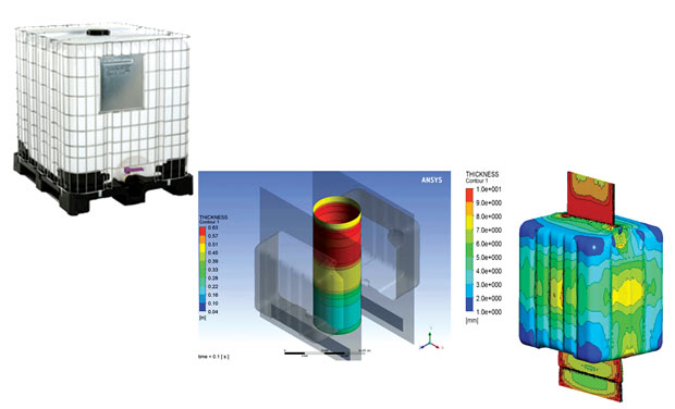 Simulating the blow molding of a 1000-liter water container completed using PolyFlow software from ANSYS.
Image courtesy of ANSYS.
Hocq says PolyFlow’s solver offers higher accuracy compared to its competitors because of its complex viscoelastic models. PolyFlow solver is a direct solver—different from iterative solvers. “Our solver might take a little more time than an iterative solver, but it can also do much more than an iterative solver can do,” he explained.
PolyFlow’s solver supports GPU acceleration. It uses the NVIDIA CUDA (compute unified device architecture) library. The program works faster on hardware with single or multiple Tesla GPUs, NVIDIA’s product line for high-performance computing (HPC).
Plastic Extension
PTC’s Creo Parametric (formerly Pro/ENGINEER) offers plastic molding simulation through the Creo Mold Analysis (CMA) extension, developed by PTC partner Moldex. Describing the product, PTC writes: “As a material, plastic has a certain charm: It’s lightweight, inexpensive and can be molded into almost any design. But just wait until that first warped or blistered part emerges from the mold. Designing a part so it can be manufactured easily and efficiently is critical to your product’s success.”
PTC Creo Parametric software comes with basic plastic analysis functions, including “3D thickness check to analyze your model’s geometry and fix basic issues,” the company states. The CMA Extension goes a step further. It lets you “quickly and accurately simulate the injection molding of plastic parts within PTC Creo Parametric … you can also perform such analyses as moldability, sink mark and weld line,” according to the company.
The common challenges with plastic design are designing for strength and cosmetic appeal, says Russell Hsu, CAD product manager at PTC. “For example, the wall thickness of plastic parts shall be as uniform as possible,” he says. “Thick walls are subject to weakness that could result in undesirable characteristics like higher stress areas, shrinkage, sink marks, and voids. Cosmetic appearance of a product’s external components is often a significant factor in quality perception, but can also lead to high production cost.”
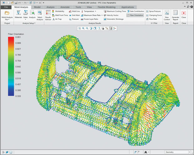 The PTC Creo Mold Analysis extension offers plastic mold simulation, including the effects of fiber orientation. Image courtesy of PTC.
Software performance is often an issue with mold simulation. But the highly parallel computation involved is an opportunity for the GPU and clusters. Both PTC Creo Parametric and its companion CMA extension are GPU-accelerated. If a GPU is present, users will see an improvement in Creo Parametric’s anti-aliasing, lighting and enhanced shaded-with-edges display mode, Hsu explains. The extension also supports batch run and cloud computation.
More CAD-Integrated Simulation
In 2008, Autodesk paid $297 million to purchase Moldflow Corporation, which develops specialized software for simulating plastic injection. Announcing the acquisition, Autodesk CEO Carl Bass said: “Autodesk sees plastics and composites as some of the fastest-growing engineering materials. Given its relatively low weight and durability, plastic materials are ideally suited to help our customers attain their sustainability initiatives. Moldflow, with its industry-leading plastics simulation, is a natural extension of Autodesk’s Digital Prototyping solution.”
Today, Moldflow software remains the leading plastic analysis package in Autodesk’s portfolio. It’s offered as Moldflow Design, Moldflow Advisor and Moldflow Insights. Developed to test, modify and verify designs with real-time feedback, Moldflow Design is integrated with CAD packages. Moldflow Advisor helps identify defects, best injection location and simulation and design strategies. Moldflow Insight offers advanced features for in-depth injection studies, Polymer flow, mold cooling, part warpage prediction, model meshing and process parameter controls.
Describing the latest release, Moldflow 2017, Autodesk writes: “Using microcellular injection technology [known as MuCell in the trade] and chemical blowing agents can help you with lightweighting parts without compromising strength. We’ve improved support for foaming technologies including MuCell with core back.”
Automotive, medical and consumer packaging industries rely on MuCell to create lightweight parts with high strength and stability. In Moldflow 2016, the product includes 3D analysis of MuCell making it easier to visualize what happens to parts with complex geometry in the process.
In conducting mold and structural analysis, Moldflow takes into account detailed material information, including fiber direction and orientation. This is a useful feature for those working with manufactured fiber-filled plastics, whose strength and tension are influenced by the fiber layout.
For complex jobs that require more processing power than what’s available in your own local machine or network, Moldflow offers the option to send the job to the cloud. The option is available for some of the most compute-intensive phases and operations of Moldflow, such as meshing, solving and design of experiments (DOE). The cost—the estimated number of cloud credits the job will consume—is displayed before the job begins.
SOLIDWORKS, a rival to Autodesk in CAD software, offers plastic analysis in SOLIDWORKS Plastics, part of the company’s simulation software lineup. According to the product data sheet, SOLIDWORKS Plastics “predicts how melted plastic flows during the injection molding process [and] part warpage and mold cooling optimization. Users can change part or mold geometry, processing conditions, or the plastic material to eliminate or minimize potential defects, saving energy, natural resources, time and money.”
SOLIDWORKS Plastics comes in three different levels: Standard, Professional and Premium. The Standard version is fully integrated with the SOLIDWORKS CAD package, and can simulate the fill stage of cavity domain. Additional features to a single-cavity analysis are available in the Professional version including multi-cavity, family mold layouts, sprues, runners and the capability to simulate the Pack stage. The higher-end Premium version lets you simulate the cavity-to-mold heat transfer during the cooling stage, molded part deformation due to plastics warpage and more.
New Frontiers
Encouraged by advances in metal-based 3D printing, some automotive and aerospace manufacturers are currently exploring additive manufacturing’s (AM) potentials for mass-production of end-use parts. If the early initiatives prove successful, what used to be a prototyping and mockup building technology could become a full-scale industrial process.
“The use of 3D printing to produce final parts is going mainstream among the manufacturing industry; this includes plastic or metallic parts. With the development of new materials, the notion of 3D printing the final product is more appealing to many companies. Another aspect of this is that several companies are 3D printing the mold to produce plastic parts,” says Jose Coronado, CAD product manager at PTC.
ANSYS’ Hocq continues working to make mold simulation more accessible to novices and non-experts. The key, he believes, is in teaching the software “to identify the right convergent strategy or the angle of attack based on user input. Once that’s identified, you can apply brute force approach to solve the equations.”
More Info
Subscribe to our FREE magazine, FREE email newsletters or both!
Latest News
About the Author
Kenneth Wong is Digital Engineering’s resident blogger and senior editor. Email him at [email protected] or share your thoughts on this article at digitaleng.news/facebook.
Follow DERelated Topics


