| UGS’s Product Manufacturing Information (PMI) has been discussed in previous CAM stories as one of the promising tools for doing away with 2D drawings for CAM programming, and for providing geometric, dimension and tolerance (GD&T) data directly to CAM programs. Although it has begun to do that, in bringing a measure of automation to NX Machining (formerly UG CAM), its biggest benefit so far has been in helping user companies remove drawings from supplier communications and speed decision-making in the 3D world.
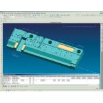 › › The feature-based automation tools in NX Machining can leverage data applied as PMI fasteners in design. The table at the bottom of this image gathers and organizes data for holemaking requirements.
PMI can be viewed as part of a native MCAD file (for IDEAS and NX) or, in lightweight JT format, can carry manufacturing information, associativities, and such attachments as text definitions, to answer questions about how to build the product—in a collaborative environment. The manufacturing information once existed only on 2D drawings, but PMI associates it with the 3D model. Replacing the Universal 2D Drawing “People are used to 2D drawings,” says George Rendell, director of Design Product Management for UGS. “Wherever you take them in the world, people understand the symbols used on them and can manufacture from the drawings. They’re almost language-independent. But now, if we want to take the next steps in design and manufacturing, we have to get people to understand how to use the same information in 3D form.”
That understanding, he believes, must spread from engineering departments throughout companies, to suppliers, and to the manufacturing floor. Just as solid 3D models made product information more understandable to such internal departments as purchasing and helped make their work more efficient, UGS and many of its customers believe that providing manufacturing information associated with the 3D model will add efficiency to the supply chain and NC programming.
PMI can contain GD&T, weld symbols, text, holes, and fasteners—and it can exist on 3D models in the same way the same information exists on 2D drawings, using leader lines that connect the data to the specific parts of the design, and make the information understandable by people new to 3D modeling. Because viewing this kind of information in 3D raises more challenges than 2D, users can put the PMI data into a logical order to indicate the front, side, or back views.
Within NX products, some of the PMI data can go directly into NX Machining—specifically data related to holes and fasteners. The process is automatic. A user first defines the PMI piece he wants, in the MCAD program. NX automatically changes the menu from MCAD to CAM, and the CAM program identifies what it can generate from the PMI data.
“Actually, the software accesses text data in the part file,” says Rendell. “The text tells users the type of fastener they’ve chosen, along with such related information as the depth of the hole into which it goes, radius, threads, and so on. It interprets and processes the data to create manufacturing information, while giving users tools to see what has been done, and to make manual changes if so desired.”
Feature-Based Manufacturing Using PMI Derek Hart, product manager for NX Machining Products, works with machining applications at customer locations. He reports that all the customers with which he works “are interested in all the information provided by PMI for machining and assembly.”
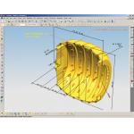
› › This is a cutaway image of the Dyson “ball” in their latest vacuum cleaner, showing PMI information displayed along with the solid model. .
He says that the first thing they want is information that’s available and visible and capable of being interrogated—the latter being impossible with drawings. “They want that information asso- ciated with the solid, not just on a drawing rolled up in tube that they can spill coffee on. PMI speeds up manufacturing processes even without any further software—including CAM—involvement.”
Hart points out that NC programmers are primarily interested in tolerances, surfaces, and the planes, points, and lines from which the parts are measured for inspection. “This information has implications regarding machine fixtures that hold the part, for example,” Hart says. “In feature-based automation, it made sense to start with holes, and we began that three or four years ago.”
While UGS is not the only company to provide feature-based machining of holes, NX Machining also uses that information to automate fastener selection. “The software looks for the geometrical attributes of features and uses them to create an automatic process to extract depth and diameter, automatic tool selection, and machining speed,” he says. “The topology of the various types of holes, including such information as positioning, diameter, tolerance, balance, and so on, that used to be found on 2D drawings, are now in PMI.”
At a higher level, Hart adds, PMI tells the software what hole will be used for what—because the necessary precision of machining will vary if the fasteners are dowel pins, screws, or bolts. “PMI fastener information can reach down and choose the right machining process, and also leave room for the user to customize. Each user has specific machines and knowledge gained from process experience, and the system can be customized to include that. It also contains standard ones in the software, making it easier for the user to tweak the system and make it right for particular processes.”
PMI will soon provide the foundation for automating such prismatic features as surfaces and flat planes. Hart says that automation will grow on the basis of what will have the most direct impact on knowledge.
Current Applications PMI and its associated technologies are sufficiently new for companies that are developing applications for it and they prefer to remain anonymous for competitive reasons. Its quickest area of growth so far is in the PLM-related arena of collaboration, because the PMI data associated with the MCAD file can be incorporated in a JT file for sharing.
For example, a large automotive OEM that still uses 2D drawings to communicate with Tier One, Two, and Three suppliers, has a new program to use 3D PMI annotation instead. After a period of getting used to the new format, the company reports that acceptance is growing.
“Particularly on the design side,” says Rendell, “two large suppliers have used PMI for over a year and report more efficient design turnaround on engineering changes.”
Another automotive OEM and a manufacturer of printing presses are currently studying PMI for manufacturing automation—but Rendell says that the system is too new for them to speak about it publicly.
In both CAM and PLM applications, PMI promises to bring manufacturing information much closer to the design cycle, and perhaps even make it part of that cycle.
Contributing Editor Louise Elliott is a freelance writer based in California. Offer Louise your feedback on this article by clicking here. Please reference “PMI, November 2005” in your message.
Product Information UGS Corp.
Plano, TX
|


