Predicting Cracks & Chinks
Research engineers at Beasy Software have developed a program to accurately simulatecracks and failures in structural material.
Latest News
November 1, 2004
By Thomas Curtin and Sharon Mellings
 Research engineers at Computational Mechanics, a division of Beasy Software,have developed a new program to simulate cracks and other failures in structuralcomponents. Using the BEM (boundary element method) of solving problems, the BeasyFatigue Crack Growth software can analyze stress field singularities ahead ofcrack fronts. (For more on BEM, see Des ktop Engineering, August 1999.)
Figure 1: Beasy Fatigue Crack Growth software analyzes stress field singularitiesahead of crack fronts and is compatible with MSC.Patran and UGS Corp.‘s modelingenvironments.
To compute mode I, II, and III stress intensity factors, special crack frontelements directly acco unt for the variation in the displacement field near thecrack front. This unique technology provides engineers with the capability toanalyze an array of crack shapes using complex geometry. In addition to its ownmodeling environment, the software can interface with MSC.Patran and UGS Corp.‘smodeling environments so that engineers already familiar with these modeling environmentsdo not need to learn another pre- or postprocessor.
|
|
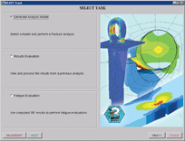
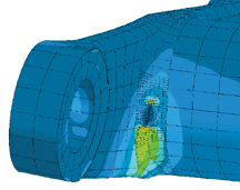
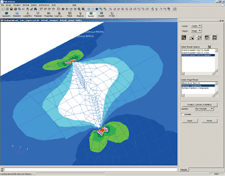
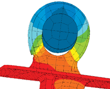
Figure 2, above: The Crack Wizard allows users to add a crack into a model tocalculate its effect. | Figure 3: A rotorcraft propulsion component with a crack growing in a fillet. |
To reduce the complexity of performing a fracture analysis, Computational Mechanicshas also developed customized “crack wizards” that guide users through the processof adding a crack into a model (see Figure 2). The software quantifies the fracturemechanics behavior for the “real part” without any simplifying assumptions. Thereare no restrictions on component geometry, loading, or crack shape. The softwarecan be used to perform a simple stress intensity factor calculation or it canperform cutting-edge, 3D crack growth studies.
|
| |
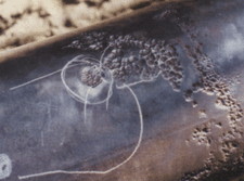
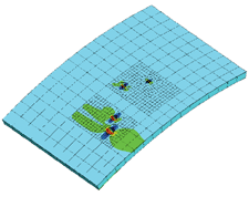
Figure 4A (top): These are corrosion pits found in a pipeline. Figure 4B (middle):A 2D pipeline model with multiple corrosion pits. A crack growth simulation wasperformed from the bottom of two of the pits. Figure 4C (bottom): The 3D modelshows corrosion pits in a curved plate. | ||
|
| |
Analyzing Structural Damage
Material properties of structu ral components tend to degrade over time as aresult of cyclic loading, fluctuations in temperature, or corrosive environments.This degradation of material integrity can manifest as discrete flaws in the structureor as localized loss in the section thickness of a critical support member. Oncestructural damage has been identified, it is important to accurately evaluateits impact on the continued safe performance of the structural components. Becausestructural damage is often related to fatigue, which can result in the initiationand growth of cracks, it is critical to evaluate the impact of fatigue loadingon structural performance.
In addition to fatigue, the ability to simulate the mechanics of fractures playsan important role as well. This is especially true when examining damage tolerance,an approach used to analyze fatigue cracks in aircraft structures. The objectiveof the damage tolerance approach is to detect cracks in principal structural componentsbefore they have the chance to propagate to failure. This approach, originallyinitiated by the military aircraft industry, is now also a standard of practicein the commercial aircraft industry. Crack Wizard is designed so engineers canselect a crack-growth equation, define fatigue crack growth material data anda load spectrum, and then submit a job for analysis (see Figure 1). The solverpredicts the number of load cycles required to grow the crack to failure. Aerospaceengineers are currently using the software to perform crack growth studies, determinecritical crack sizes, and estimate remaining service life for principal structuralcomponents. They can then use the analysis results to develop appropriate inspectionintervals for aircraft.
Crack growth behavior in rotorcraft tends to be slightly more complex than thattypically found in fixed-wing applications (see Figure 3). Rotorcraft structuresexperiencing high-frequency cyclic loads are subject to more variable and complexflight load spectra. These flaws tend to be very small, irregularly shaped, andare often positioned in difficult-to-inspect locations. As a result, it is importantto analyze these flaws so that acceptable service inspection intervals can bedetermined. The program’s crack-growth technology allows users to predict themost likely crack-growth path, which is useful information for nondestructivetesting experts charged with searching for flaws in components.
Fitness for Service Assessment
Structural components are often subjected to unexpected service loads or areleft in service beyond their intended design life. When this happens, unexpectedfailures occur causing engineers to become forensic scientists in order to uncoverthe factors contributing to the failure. The Beasy Fatigue Crack Growth softwarehas been used extensively to perform forensic studies to help engineers betterunderstand why a component failed and to provide information that can help withthe redesign process.
Because many industrial systems and infrastructure across the U.S. are approachingthe end of their original design life, it is important to be able to estimatetheir remaining safe-service life. Fitness for service assessment uses analyticalmethods, mainly stress analysis, to evaluate flaws such as locally thin areas,cracks, and corrosion pits as well as damage such as dents, bulges, and distortions.Fatigue Crack Growth software is well suited for analysis of both planar and volumetricflaws in pressure vessels, piping systems, and storage tanks. Thus the softwareis well suited for the fitness-for-service arena as a flaw evaluator to help characterizethe structural integrity of in-service components.
Structural integrity analyses conducted using the API Recommended Practice 579Fitness for Service code require the development of a failure assessment diagram.Most failure assessment diagrams are developed using stress intensity factorscontained in handbooks, but these are often limited to simple geometry and loadingconditions. Using the Fatigue Crack Growth software, engineers can calculate stressintensity factors for the actual geometry and loading without any simplification.This leads to a more accurate failure assessment diagram because the impact ofthe real flaw on the mechanical strength of the pipeline is under scrutiny. Thisresults in more reliable estimates of the safe operating loads for in-serviceequipment.
Further, Into the Pits
Research engineers at Computational Mechanics are currently investigating betterways to analyze volumetric flaws such as corrosion pits (see Figures 4A, 4B, and4C). Recent work has been promising and the company envisions that the Beasy softwarewill soon be able to simulate the impact of pitting, not only for pipelines andstorage tanks but also for corrosion-susceptible aerospace components. The ultimategoal will be to simulate the interaction between multiple corrosion pits and initiatecrack growth from the root of a corrosion pit. With the advancement of this technologyit will be possible to simulate the actual mechanics of failure of corroded components.It is a lofty goal, but based on conversations with government agencies and companiesaround the globe, it is a technology that is desperately needed across a rangeof industries.
Thomas Curtin has an MSME from Northeastern University and is the applicationsengineering manager for Computational Mechanics. Sharon Mellings has a Ph.D. fromthe Wessex Institute of Technology. She is a senior research engineer for theComputational Mechanics group. You can contact the authors via e-mail at [email protected].
Notch-Induced Cracking in an Engine Mount Fitting
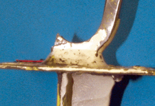
An engine mount fitting on an aircraft failed as a result of a tooling misalignmentduring the machining process. A small notch was inadvertently created at a criticalfillet location in the component (see image at left). This notch created a stressconcentration, which led to fracture of the component.
The Beasy Fatigue Crack Growth software was used to determine critical cracksizes and investigate the decrease in service life created by the presence ofthis flaw. Engineers were able to model the actual load transfer in the fittingby using a nonlinear contact analysis to simulate the behavior of the semisphericalbearing (below). The stress intensity factors were found to be very sensitiveto the technique used to model the pin load. It was not sufficient to apply anassumed pressure distribution to represent the bolt load. A contact analysis includingthe pin as part of the analysis allowed for “hole propping,” which provided themost realistic results. Using this approach, we obtained good agreement betweenthe Beasy computer simulation and the failure condition observed for the in-servicecomponent.
-TC
Product Information
Beasy Software
beasy.com
Subscribe to our FREE magazine, FREE email newsletters or both!
Latest News
About the Author
DE’s editors contribute news and new product announcements to Digital Engineering.
Press releases may be sent to them via [email protected].


