

October 1, 2005
By Arvind Krishnan
A glance at such disparate machines as pumps, table fans, axial fans for electronics cooling, and hair dryers, shows that they all have one thing in common: rotating components.
Engineers who design equipment with rotating components need to analyze and understand the behavior of those components if they want to improve performance. For example, if the blades of a table fan are the wrong shape, or if they’re incorrectly orientated, the fan may generate little or no air.
|
|
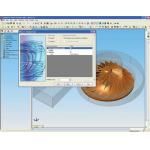
| Figure 1: This pump assembly was modeled using SolidWorks and provides a good example of how COSMOSFloWorks can be used to analyze the rotating components. |

CFD (computational fluid dynamics) helps engineers study many of the issues involved in rotating component behavior. It provides a way to save a great deal of time and money in obtaining the necessary information, and assists engineers in designing better quality rotating equipment.
The use of CFD makes it possible to eliminate expensive physical prototypes, and find serious flaws much earlier in the design process. Starting with some CFD basics, this article will give engineers an overview of how CFD can simulate rotational flow, and will then take a closer look at how users of COSMOSFloWorks can solve typical problems.
Approaches for Analyzing Rotating Flow
Several different approaches can be used to study flow in and around rotating equipment. In the majority of rotating machinery fluid flow analyses, engineers model the flow in a steady-state manner. The term “steady state” refers to a solution that does not vary with time.
|
|
| Figure 2: COSMOSFloWorks uses a wizard-based interface to set up the flow analysis. The user chooses the configuration and unit system. |
A very simplified approach, called Single Rotating Reference Frame, which assumes that the entire fluid domain or region rotates with the rotor or impeller, can be used to study the flow around the impeller blades. However, because this doesn’t consider any effects of the pump casing on the flow, it is insufficient for analyzing a full pump system.
To study the whole flow pattern and see the effects of the stationary pump casing, baffles, and other internal parts, users need more comprehensive methods, such as Multiple Rotating Reference Frame or the Sliding Mesh approach. Using the popular Multiple Rotating Reference Frame, also a steady-state approach, the engineer assigns zero revolutions per minute (RPM) to nonrotating components, called stators, and fixed RPMs to the rotating components, called rotors. With this method, users can consider more than one rotor, each rotating with a different RPM.
|
|
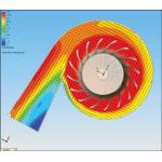
| Figure 3: This section plot with velocity vectors was created using COSMOSFloWorks once setup Wizard took the user through a number of steps. |
The Sliding Mesh method is a transient approach that is useful for rotating flow problems requiring a time-accurate solution for computing the unsteady flow field. It requires a very large number of time steps to arrive at the transient solution, making the process time consuming as well as computationally demanding, and may turn out to be impractical on desktop computers.
Using COSMOSFloWorks for Rotating Machinery
COSMOSFloWorks uses both the single and multiple rotating reference frame approaches to solve rotating flow problems. Overall, the program employs configuration-based fluid flow analysis coupled to SolidWorks assembly configurations to enable a wide variety of what-if scenarios. Every flow study either creates a new configuration or can link to an existing SolidWorks configuration. The software aims to solve the majority of possible rotating equipment problems, and to do so quickly. For the sake of speed, COSMOSFloWorks does not use the transient approach.
|
|
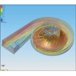
| Alternate Figure 3, not published in the hard copy of this article, showing flow trajectory plot. |
To represent the boundary of the analysis, COSMOSFloWorks automatically creates the fluid volume using SolidWorks geometry, and indicates the fluid volume visually by drawing a box on the model. This fully automatic step saves the engineer a considerable amount of time, compared to the necessity with many other CFD programs to simplify the MCAD model and create the fluid volume manually.
For example, to analyze the pump shown in Figure 1 (above) for head or volume flow, if the impeller rotates at 2000 RPM, the user would work with a pump assembly model in SolidWorks, accessing COSMOSFloWorks via a menu heading in SolidWorks, and follow these steps:
|
|
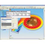
| Figure 4: The flow analysis goals (head, volume flow rate, pump efficiency) are output in Excel format once the computation has run. |
• The user selects the Setup Wizard from the COSMOSFloWorks menu, and first chooses the configuration he wants for the analysis, as well as the unit system desired (Figure 2, above).
• When the Wizard offers a choice of internal or external flow analysis, the engineer faces a number of choices. In the case of the pump, he selects internal rather than external flow analysis, and then activates “rotating flow.” Because this analysis studies flow behavior not only around the impeller, but also inside the casing, the user needs to use the multiple rotating reference frame method and he selects local regions rather than global to launch that method. If he has any heat transfer to consider, he has the option of including it by turning on a flag indicating “heat conduction in solids.”
|
|
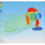
| Figure 5: This table fan is another example of a rotating machinery application that can be analyzed using the COSMOSFloWorks CFD solution. |
• Next, the engineer selects the working fluid, which in this case is water. The program has a library of commonly used liquids and gases from which to choose, or the engineer can create his own library of frequently analyzed fluids.
• In the final step in the Setup Wizard, the user selects the resolution of results he wants on a scale from one to eight. The higher the number the more refined the mesh will be and the more accurate the results.
• Using dialog boxes in COSMOSFloWorks, the user then specifies a rotational speed for the rotating region. As mentioned above, the speed in this case is 2000 RPM. The engineer supplies a boundary condition that designates the pump casing walls as the stator, and applies environmental pressure boundary conditions at the inlet and outlet.
The program enables goal-based analysis, so before running the analysis, the user chooses his goals, which, in this case, may include pressure drop between the inlet and outlet to determine head; volume flow rate at the inlet to determine the volume rate; and torque on the impeller to determine the pump efficiency.
|
|
| Alternate Figure 5, not publishied in the hard copy of this article. |

COSMOSFloWorks automatically creates the mesh and iterates to a converged solution. The analysis provides information on the head and volume flow rate generated by the pump at 2000 RPM, and determines the efficiency of the pump. From that information and the needs of anticipated pump users, the user can conduct as many what-if studies as desired, analyze them, redesign the impeller blades, and select the best impeller blade design for maximum efficiency.
Users and others can view the goals, and create a number of different plots for viewing results, along with an AVI showing the flow trajectory.
Many other rotating flow applications exist in many industries. Just a few include jet engines, electronics cooling fans, marine engines and pumps, chemical blenders, and consumer products such as hair dryers. Users follow the same steps described here to analyze the pump, and as in that example, results can be used to refine and improve designs.
Arvind Krishnan is the product manager for COSMOSFloWorks at SolidWorks Corp. Send your comments about this article through e-mail by clicking here.
Product Information
COSMOSFloWorks
SolidWorks Corp.
Santa Monica, CA
Subscribe to our FREE magazine, FREE email newsletters or both!
About the Author
DE’s editors contribute news and new product announcements to Digital Engineering.
Press releases may be sent to them via [email protected].


