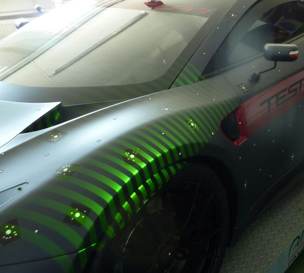
Projected patterns.

Latest News
July 31, 2017
The project of the first Polish supercar, Arrinera Hussarya, from the very beginning, has been arousing strong emotions and hopes that the Polish automotive industry will come back to its past glory. The production of functioning prototypes that at the same time has to achieve the level of a sports car requires precision and durability.
Unlike most contemporary Polish automotive projects, Arrinera Hussarya is built from the ground up. All parts of the car body, engine and interior, despite the fact that they often use proven technologies, are redesigned to not only meet all the requirements but to also represent the aesthetics worthy of a supercar.
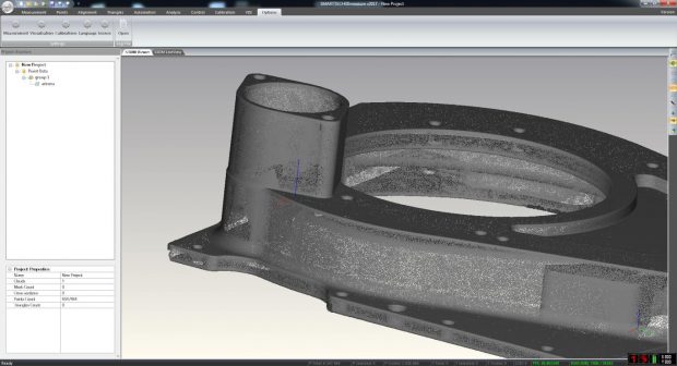
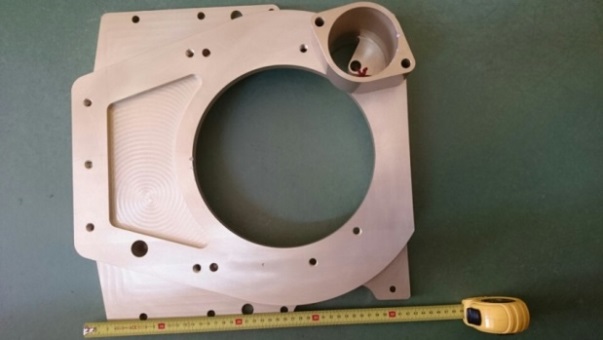 Housing used as the basis of the project.
Reverse Engineering Reduces Production Costs
Redesigning a supercar is not only a very time-consuming but also an extremely costly process. The Arrinera engineers long searched for ways to accelerate the development and reduce the costs. They finally decided to use reverse engineering, which is the process of reconstructing the technical documentation of an existing element in order to re-design it.
By implementing a professional SMARTTECH 3D scanner, the engineers working on the supercar gained the ability to quickly obtain comprehensive information about the geometry of the car parts. An excellent example of the capabilities of the 3D scanning technology is the process of designing and manufacturing a clutch housing.
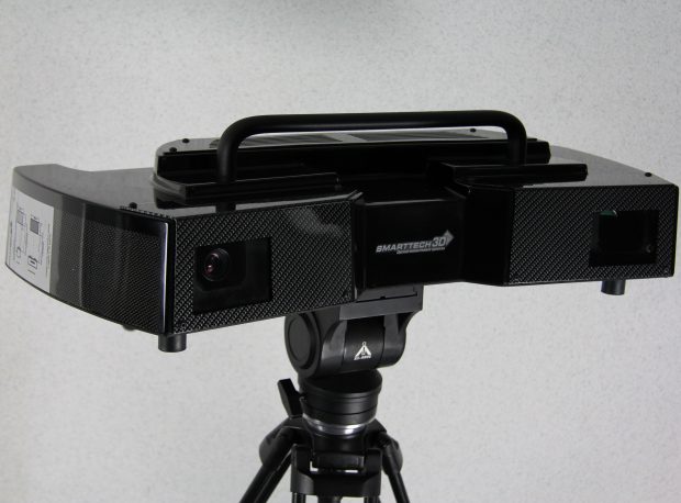 MICRON3D green.
It is no secret that a sports clutch is subjected to completely different pressures than a normal clutch working in a standard car. An 810 Nm torque requires the use of not only a reliable but also lightweight clutch design. The 3D scanner made it possible to obtain the technical documentation of a housing already present on the market and redesigning it in the CAD software in order to install the mounts fitted to the vehicle’s structure.
Green Light is the Future
 Projected patterns.
A 3D scanner MICRON3D green with 10 megapixel detector was used for accurate measurement. The technology based on the green LED light allows the measurements to achieve 30% better results than when using 3D scanners with white light. With a field of view of 800 x 600 mm, the 3D scanner obtains a point cloud representing the scanned shape with 0,084 mm accuracy.
In practice it means that with a single measurement you can scan an area equal to 80 x 60 cm. Unlike other solutions available on the market, the SMARTTECH 3D scanners are permanently calibrated with one measuring volume. This solution ensures that the user can set to work without needing to calibrate the device. It not only saves time but also eliminates the problem of calibration influencing the accuracy.
The MICRON3D green is also metrologically certified in accordance with the German VDI/VDE 2634 standard giving Arrinera the confidence that the measurement error does not exceed the values given in the device’s accuracy certificate.
 Measurement result representing the clutch housing.
3D Scanners are Metrological Devices
The measurement performed by a SMARTTECH 3D scanner is based on the projection of patterns on the measured surface. The patterns deform depending on the curvature and are recorded by a detector integrated in the measuring head. The device measures only the surfaces that are visible to the detector. In order to obtain a comprehensive information about the geometry from every angle the object needs to be scanned using a rotary stage. The load capacity of the rotary stage is over 300 kg while its diameter is 50 cm, which is sufficient to perform complete measurement of most car parts.
The image from the detector is then converted into a point cloud thanks to a special software algorithm. Each of the points contains information about the geometry described in the X, Y, Z coordinates, which after post-processing can be used for quality control or – as in the Arrinera case – to redesign and mill the model on a CNC machine.
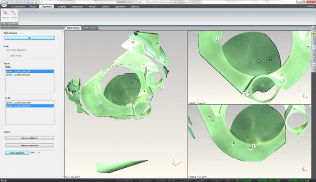 Alignment of measurements using the „three-point” method.
Depending on the resolution, the point cloud from a single measurement can consist of 5 or 10 million points for a resolution of 5 or 10 megapixels, respectively. The number of megapixels affects the extent of detail obtained from a given object. In Arrinera’s case, a 3D scanner with a 10 megapixel detector was used since there was a need to accurately reproduce the edges of the measured object.
The clutch housing was scanned from two sides, which allowed to obtain two point clouds. For each point cloud there were six individual measurements. Using a rotary stage integrated with the 3D scanner the individual measurements were preliminarily aligned. An alternative option consists of for e.g. using positioning markers.
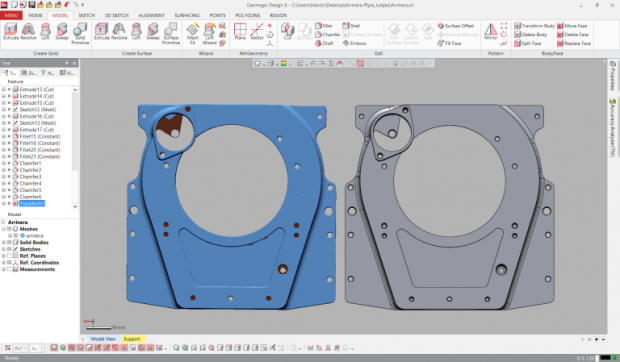 Triangle mesh and CAD model created on its basis.
Aligning Point Clouds in the Software
After the scanning process it is possible to convert the point cloud into a triangle mesh in the software SMARTTECH3Dmeasure. The software is provided with every SMARTTECH 3D scanner. Before the conversion, we first need to align the measurement results.
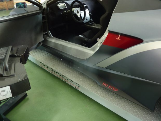 Car sill.
For the alignment we used the „three-point” method where we selected three common points for both point clouds. Based on this the software automatically determined the results’ position to one another. The goal was to obtain a point cloud completely representing the scanned object. The use of a rotary stage significantly simplified the operation of the alignment of the results because it divided it into two groups of points representing each of the sides.
Before converting the point cloud into a triangle mesh we need to use the function of „Global alignment”, which based on the position of the points will precisely align all the point clouds to one another. At this stage we also have to remove the overlapping, which are overlapping areas of different measurements.
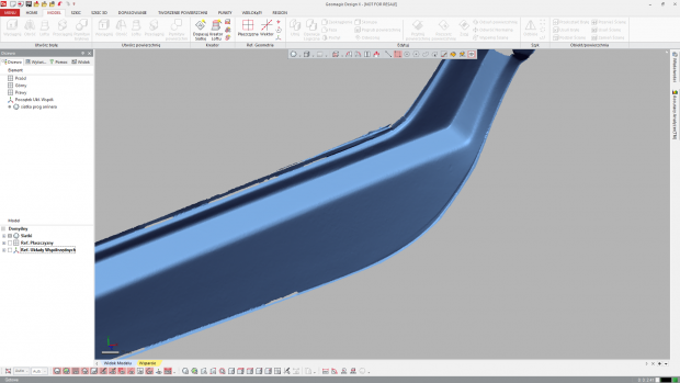 Car sill in the form of a triangle mesh.
After these operations the point cloud is then converted into a triangle mesh. For Arrinera the STL format was chosen, which is the most popular format for triangle meshes because of its compatibility with 3D printers and milling machines. The triangle mesh can also be used as a base for CAD modelling. Arrinera made and adjusted the CAD model and then sent it to software operating a CNC machine. The 3D scanning not only reduced the strain on the company’s budget but it also enabled the manufacturing of a dedicated part.
Scanning Large Objects with Positioning Markers
The 3D scanning on a rotary stage in a measurement laboratory isn’t always possible due to the size of the object. In such a situation you can make measurements on the production line thanks to the alternative method using positioning markers. The second example talks about this method. During the production of the first copy it is often the case that, despite the long-term design process, not all parts are exactly the same as they were originally planned.
The Arrinera engineers were faced with that problem. The left sill of the car was adapted to optimize the structure. In order to maintain the symmetry of the vehicle the sill from the other side had to be made in exactly the same shape. The conventional measuring methods used by Arrinera did not allow it to obtain the full geometry and that is why it was decided that the SMARTTECH 3D technology would be used.
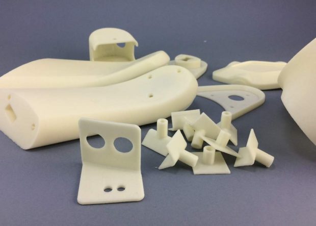 3D printed parts by OMNI3D.
The use of the MICRON3D green in the workshop is possible thanks to the housing made of carbon fiber. The protection of the precious interior is provided by a F7 class filter. The durable housing guarantees not only reliability but also stability and high quality of measurements. In addition, the internal shock absorber system suppresses vibrations that may affect the accuracy of the results.
The geometric data of the existing sill were collected directly from the physical prototype. Arrinera Hussarya stood on a platform and access to the sill was hindered by the car door. Because the sill’s dimensions were much larger than the field of view of the 3D scanner it was necessary to use a very useful scanning function with positioning markers.
The measurement method using markers relies on attaching special positioning markers on the scanned object. The software SMARTTECH3Dmeasure that operates the 3D scanner finds five common positioning markers between two individual measurements and then aligns them. The 3D scanner operator has a full view of his work and can easily add scans of the remaining parts of the sill. The sharp angle between the projector and detector enabled us – despite the cumbersome manual constraints – to obtain a large amount of data about the geometry.
The result of 3D scanning with positioning markers is a preliminarily aligned cloud point. The further post-processing in SMARTTECH3Dsoftware is done similarly every time because of its intuitive design and ability to automate individual operations. In this case it is also necessary to create a reference CAD model in the Geomagic Design X, used by Arrinera. This model is compatible with cutting and bending machines that make the necessary parts.
Having a CAD model of a given element enables the use of the 3D printing technology for rapid prototyping. Arrinera chose the solution from a Poznan-based company OMNI3D, whose flagship product Factory 2.0 Production System creates large format 3D prints in the FFF (fused filament fabrication) technology.
The device was used for rapid prototyping. The design process requires continuous improvement of the components and therefore the production of not one but several prototypes of any given part. Doing that with traditional methods consumes a lot of time and involves high production costs.
OMNI3D printed for Arrinera parts such as mirror housings and intakes in the 1:1 scale. It allowed the supercar’s manufacturer not only for rapid prototyping but also to use parts made in ABS. Thanks to the use of the 3D printer, Arrinera was able to reduce the parts’ weight which is particularly important in a supercar where the weight is one of the crucial components when deciding whether to install a particular element.
Designing and building the first racing car is not only an engineering but also a financial challenge. The 3D technologies provide both the savings in costs as well as the required precision during the data acquisition, prototyping and production adjustments. Arrinera, thanks to the use of 3D technologies, was able to significantly accelerate the prototyping process and reduce the time required for their production.
Subscribe to our FREE magazine, FREE email newsletters or both!
Latest News


