Flow and thermal analysis methods are fundamentally important to the gas turbine design process.


Latest News
October 1, 2017
By Javier Garriz, Chad Custer and Jim Ryan
Siemens PLM Software
 Flow and thermal analysis methods are fundamentally important to the gas turbine design process.
Gas turbines must be designed to produce energy as efficiently as possible, with components designed to sustain reliable operation in the extreme conditions within a gas turbine engine. Complex aerodynamic and thermodynamic interactions are a major determinant of a turbine’s performance; as such, flow and thermal analysis methods are fundamentally important to the gas turbine design process. Many turbine manufacturers still largely rely on one- and two-dimensional correlation-based approximations in their day-to-day turbine design processes, but these methods limit the accuracy of temperature predictions. Competing demands for improved efficiency, reliability, emissions and unit costs have amplified the need for tools capable of moving beyond simple correlation-based methods.
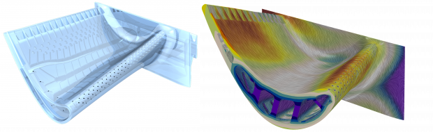 Fig. 1: Aerodynamic and thermal prediction of a candidate blade design. A. (left) Candidate blade design with complex cooling features. B. (right) Aerodynamic and thermal prediction.
Siemens PG now uses three-dimensional computational fluid dynamics (CFD) simulations to predict the complex flow-field and turbine blade metal temperatures accurately and rapidly enough to have an impact on day-to-day engineering decisions. This innovative workflow is based on the Siemens PLM Simcenter platform using NX for 3D CAD geometry generation and STAR-CCM+ software for multiphysics CFD simulation.
Results obtained with the STAR-CCM+ Conjugate Heat Transfer (CHT) CFD simulations are highly accurate, with blade metal temperature predictions consistently within 8% of experimental test values1. Dr. Jose Rodriguez of Siemens PG said, “Being able to rapidly obtain turbine blade metal temperatures that are within engineering accuracy of experimentally-measured values is enabling us to discover improved gas turbine designs, faster.”
Progressing Beyond the Traditional
The environment in which turbine blades operate is harsh, with temperatures significantly higher than the melting point of the metal blades themselves. Safe and efficient operation of gas turbines relies on the cooling provided by air routed through internal passageways built into the blades. As such, a goal of cooled turbine blade simulation is to determine metal temperatures throughout the blade. These temperatures and the predicted aerodynamic loads allow for stress predictions to be performed, and the durability of the blade to be established. Approaches to obtaining these temperatures and loads have evolved as computational methods have improved and become more practical. Each of the three analysis methods outlined as follows describes tools and process of predicting the blade temperature of a candidate blade design.
- Legacy Design System: Internal and external turbine blade flow-fields are approximated using 1D correlations obtained from experimental data and simple relations. The correlation-based results are then used as inputs to a 3D finite element analysis (FEA) to predict blade temperatures.
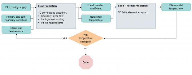 Fig. 2: Legacy Design System: 1D correlations allows for rapid flow-field prediction, but requires expensive test data and the maintenance of multiple tools. The cumbersome workflow is error-prone and requires high levels of user interaction.
The process, shown in Fig. 2, begins by specifying the cooling air being delivered to the blade and a specification of the aerodynamic conditions the blade will experience (boundary conditions). Additionally, a blade wall temperature is assumed. These inputs are used to determine the internal and external flow-field using low-fidelity methods. These flow-field estimates provide the necessary boundary conditions for a 3D finite element analysis (FEA), which will result in a blade surface temperature distribution. This analysis cycle is repeated until the predicted blade surface temperature agrees with the assumed input.
Each iteration of the analysis loop is fast due to the simplicity of the models used, however those simplifications yield lower accuracy leaving a greater uncertainty of how the actual engine will perform. The correlation methods used rely on engine test data for correlation, meaning that expensive experiments must be performed and only designs similar to what has been tested can be considered. Additionally, the analysis process relies on the maintenance of multiple tools, and a cumbersome workflow to pass data between the tools.
- CFD-based Design System: The correlation-based flow-field predictions of the Legacy Design System are replaced by separate 3D computational flow dynamics (CFD) simulations of the internal and external blade flow paths. The results from these separate CFD simulations are then used directly as inputs to 3D FEA analyses to obtain the metal temperatures.
The use of CFD in place of the correlations means that this approach allows 3D effects to be captured and accounted for in the design iterations, reducing the reliance on prototype testing. The simulations of the internal and external flows can be performed simultaneously, but are not tightly coupled. As shown in figure 3, the workflow has not changed from the Legacy Design System. The only change is that the correlation methods used for flow-field prediction have been changed to physics-based CFD models.
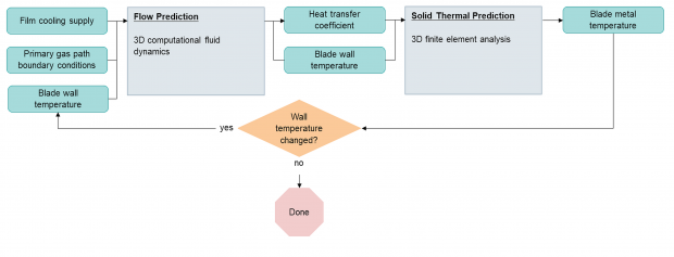 Fig. 3: CFD-based Design System: Use of 3D CFD improves accuracy, reduces reliance on test and eliminates maintenance of correlation based tools, but the analysis loop remains iterative, requires a high degree of interaction and is prone to error.
The accuracy of the method as well as the design possibilities are improved as a result of moving away from correlation methods. However, the workflow remains cumbersome and error-prone.
- CHT/CFD Design System: Performing the entire analysis within one virtual prototype platform allows for highly accurate results and a greatly simplified workflow. As illustrated in figure 4, a single 3D multiphysics simulation models the aerodynamics of the internal flow-field, external flow-field and solid conduction in a single simulation.
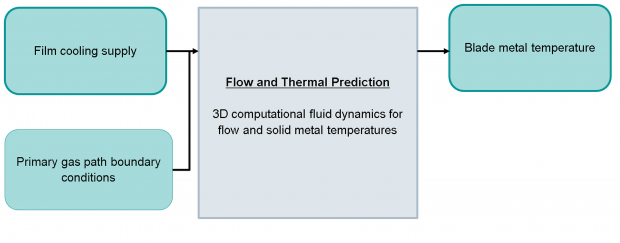 Fig. 4: CHT/CFD-based Design System: A single integrated virtual prototype platform is used to calculate fluid-flow and metal temperature. The physics-based approach allows for novel designs to be analyzed quickly and easily with little user interaction.
Performing a multiphysics simulation using the high-fidelity 3D model of the turbine blade allows for a far more accurate characterization of the system than that provided by the other approaches. Solving both the aerodynamics and solid conduction domains simultaneously further increases accuracy, while eliminating the need to iterate within the analysis process. When these modeling techniques are combined into a streamlined design system, the shortened design time allows for efficient design-space exploration and the ability to analyze truly novel designs that fall well outside the scope of empirical correlation-based methods.
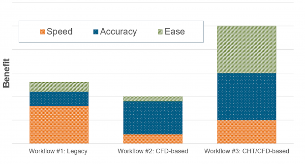 Fig. 5: Relative benefits of each workflow, highlighting the significant overall advantage of the CHT/CFD-based Design System.
The relative benefits of each workflow are summarized in Fig. 5. The overall value of the combined increases in speed, accuracy and ease-of-use associated with the conjugate heat transfer (CHT)/CFD workflow cannot be overstated, especially when it is understood that it is the only one which allows for automated exploration of new designs outside the scope of correlation methods.
Validating the 3D CHT/CFD System
Validation is important when implementing any analysis method. It is important to determine how to appropriately use the tool to model the system of interest. The Siemens team validated the CHT/CFD methodology in two stages. First, they performed simulations of individual turbine blade features and compared the results against experiments in order to determine a set of best-practices to be used for subsequent simulations. They then performed simulations of the full blade geometry under engine operating conditions using the recently developed best-practices. The engine predictions were then compared to experimental data from engine tests conducted at the Siemens Berlin Test Facility (BTF) to verify accuracy of the simulation process.
Feature validations were performed on simplified representations of specific turbine blade features, each representing a geometry and flow phenomenon relevant to the turbine blade’s operation. These fundamental tests included single and multijet impingement, turbulated ducts and pin fins. The experimental data against which these simulations were compared was gathered in controlled environments and therefore considered to have less uncertainty than the data gathered from full-on engine validations. The sensitivity of the flow simulations to mesh refinement and turbulence model selection was systematically examined, providing insights into the settings that might prove most effective in the full turbine blade simulation.
For the second validation stage, measurements were taken of the solid blade temperature of an H-class engine’s vane 1. This engine test was conducted at the Siemens BTF. The blade temperature was measured using more than 1,500 micron-sized thermal crystals embedded into a total of 12 vanes.
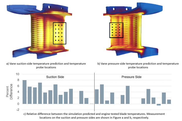 Fig. 6: Predicted blade temperature on the suction and pressure sides of the vane and the relative difference between the predicted and observed temperatures.
The full-fidelity geometry of the experimental blade was simulated under the same operating conditions as the test. Figure 6 shows the complex geometry of the blade used in the full blade CHT/CFD simulation, along with the predicted blade temperature and flow-field on the suction and pressure sides of the vane (shown in Fig. 6a and Fig. 6b, respectively). Temperature measurement locations are marked as black points on the surface of the vane. The relative difference between the predicted and observed temperatures is given in Fig. 6c and show that the difference between predicted and observed temperatures is small, with a maximum deviation of 8%. This is particularly good agreement considering the strong thermal gradients in the vicinity of the probes. Small differences in the local flow-field and heat transfer would result in large changes in the predicted temperature.
Conclusion
The integrated CFD/CHT workflow developed by the Siemens team based on Simcenter technology is an integrated and automated analysis process capable of accurately predicting turbine blade metal temperatures of novel blade designs. The method provides detailed physical insight within the time constraints imposed by a tight production schedule. The integrated, 3D, multiphysics-based approach represents a more accurate characterization of the system, enabling engineers to analyze and explore novel concepts well outside the scope of correlation-based methods—a significant progression beyond traditional workflows.
The automated, pipelined workflow based on NX and STAR-CCM+ also means that the Siemens engineers can quickly perform simulations of multiple design variants, to assess the effects on the metal temperatures due to changes in geometry and/or flow conditions.
“Our use of STAR-CCM+ with NX has enabled us to streamline our workflow and obtain way faster thermal prediction capability for our gas turbines, impacting our day-to-day design iterations,” Philipp Cavadini of Siemens PG says. “Now we are looking forward to leveraging additional data management technology, such as Teamcenter for efficiently managing the large quantities of product models and simulation data.”
Reference
- Jose Rodriguez, Philipp Cavadini, Marco Brunelli, Chad Custer and Cassandra Carpenter: High Fidelity CHT CFD for Gas Turbine Heat Transfer Applications, Proceedings of the 1st Global Power and Propulsion Forum (GPPF), Zurich, Switzerland, January 2017.
Subscribe to our FREE magazine, FREE email newsletters or both!
Latest News


