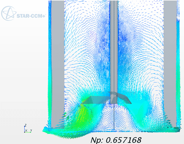
Figure 3: Velocity vectors and power number.
Latest News
August 1, 2016
By N. Chastan, Pierre Guerin SAS
Like many successful entrepreneurs, Pierre Guerin founded a small family business of five employees for agricultural and dairy maintenance equipment in 1949. It took decades of evolution of products, brands, contributions and innovations to turn his startup into a successful corporation, which is now recognized as the major European supplier of stainless steel process mixing vessels for the chemical/food/beverage and pharmaceutical industries. For these industries, mixing is a key unit operation as the quality of products is highly dependent on how effectively and efficiently the components with different properties mix with each other in order to reach a uniform blend with desired attributes.
For Pierre Guerin to maintain its competitive advantage in the market, it is crucial that they design and manufacture equipment that guarantees the highest level of mixing quality while keeping operational time and cost as low as possible for its customers. In this case, traditional scale-up approach from lab scale to production has been never an easy task. It involves time consuming, and expensive, experimentations to test and verify any new ideas during the design process.
CFD simulations provide a robust tool for modeling the system in actual plant scale that also captures all key physics and required quantities in continuum space, explore the design space faster, and hence reduce the number of trials required for optimization of stirred tank.
In this way, engineers are able to submit only the most promising design to physical testing. In mixing vessel applications, some of the main targeted characteristics are the pumping number, the power number and the mixing time. In order to select the most efficient CFD tool to predict these numbers, mixing engineers at Pierre Guerin conducted validation studies using several CFD software tools, including STAR-CCM+.
This article outlines the comparison between the numerical results of STAR-CCM+ and experiments carried out to validate the behavior of the company’s patented propeller. A similar validation study on a Rushton turbine has also been performed and documented in the past [1].
Geometry and Mesh
STAR-CCM+ can be used to model different types of impeller/vessels manufactured by Pierre Guerin (Fig. 1). In this study, the geometry is composed of a flat bottom vessel with four baffles, and a Pierre Guerin HTPG4 impeller (Fig. 1a). Vessel geometry and baffles were created using STAR-CCM+’s 3D-CAD modeler, and the impeller was extracted from a neutral CAD file format using the STAR-CCM+ surface wrapping functionality, which was used to produce a closed volume from which as automated 3D unstructured polyhedral volume mesh was generated. One major advantage of the polyhedral meshing approach is that the polyhedral cells have many neighbor cells (typically of the order of 10). This allows transfer of variables across neighboring cells more efficiently. They can better capture the intricate geometry at a much lower cell count than the tetrahedral mesh. The lower number of cells result in lower computational requirement.
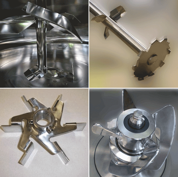 Figure 1: Different of impellers manufactured by Pierre Guerin: Low shear HTPG4 propeller for Cell cultivation (top left); Heli Turbo Agitator HTA for powder dissolution (top right); Rushton turbines for aerobic fermentation (bottom left); Magnetic mixer PG-MAG for ancillary vessels (bottom right).
Also, the global/local refinement capabilities of polyhedral mesh, along with the prism layer mesher at the boundaries, enabled engineers at Pierre Guerin to accurately capture the flow around the impellers, a key requirement for accurate power calculation. Fig. 2 illustrates the computational mesh depicting fine mesh in the impeller region as well as boundary layers along the walls. The domain is divided with an interface between the outer stationary frame, attached to vessel wall, and the central rotating part around the impeller. This resulted in 400K cells in the domain.
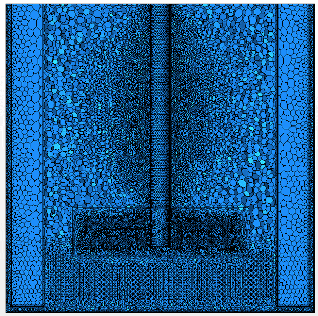 Figure 2: Polyhedral mesh in the computational fluid domain of the vessel and HTPG4 impeller using STAR-CCM+.
Assumptions and Boundary Conditions
The process fluid for simulation was considered as a single-phase liquid with constant density. The Moving Reference Frame (MRF) method was used to simulate baffled stirred tank rotation [2]. The impeller motion was modeled using the “rotor-stator” approach.
To model rotation of the shaft, the shaft part in the stator domain has a relative rotational speed in the opposite direction. RANS (Reynolds Averaged Navier-Stokes) approach was used for turbulence modeling using the realizable k-ε two-layer model. It is not essential to know the flow detachment near the impeller blades. Therefore, there is no need to solve the viscous sublayer equation. But the boundary layer plays a role in the gradient generation; the buffer layer has to be solved. Use of this model has been verified with the wall y+ calculation, on the impeller and the shaft. Wall y+ was between 1 and 20. Because of the constant density flow and its incompressible character, the segregated flow solver is selected.
In order to evaluate mixing, STAR-CCM+ provides passive scalar approach. Passive scalars are user-defined variables of arbitrary value, assigned to fluid phases or individual particles with no appreciable mass or volume, and no effect on the physical properties of the simulation. It is also possible to define and inject more than one passive scalar in the domain. This capability is useful to trace a numerical dye injected in the flow stream as well as to analyze the mixing of two or more fluid streams that have the same properties.
In this study, once the steady state solution was achieved, the flow solver was frozen, and the passive scalar transport equations were solved using implicit unsteady calculations and rigid body motion solver. The implicit unsteady solver equations have been solved using the 2nd-order upwind scheme.
Results
Convergence within the order of 10e-4 is achieved in about 17 minutes with a four-core parallelization of the computation. Fig. 3 shows the numerical velocity vector field with an upward flow direction close to the walls/baffles, and a downward flow direction close to the impeller shaft. Numerical results of velocity field are available throughout the entire domain at any desired cross sections. Experimental measurement does not allow measurements in the full continuum of flow field data, and the engineering analysis is limited to the finite number of points at which measurements are taken. Access to the velocity and other fields in the domain gives valuable insights into the flow patterns and mixing behavior in the system.
Power & Pumping Number
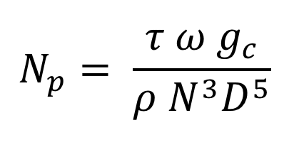
In order to verify the accuracy of STAR-CCM+ to predict the mixing performance, engineers at Pierre Guerin calculated characteristic numbers: power number, pumping number and a dimensionless mixing time. These numbers are unique to geometrical configurations as well as operating conditions. In order to calculate power draw unique to each type of impeller, the dimensionless number is defined as the power number (Np) that is calculated using the following formula:
Where τ (N.m) is the resulting torque, ω (rad/s) is the impeller angular speed, N (rpm) is the impeller rotational speed, ρ (kg/m3) is the density, D (m) is the impeller diameter and gc for the gravitation constant.
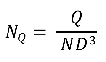
Another dimensionless number which is used to calculate the flow or pumping rate unique to each geometric shape of mixing impeller is the pumping number (NQ). It can be calculated using the following formula:
Where Q (m3/s) is the flow generated by the impeller, N (rpm) is the impeller rotational speed, and D (m) is the impeller diameter. These numbers are numerically calculated and are compared with experimental results in Table 1. As can be seen in this table, the results from STAR-CCM+ are in remarkable agreement with those of the experiments as the percentage of difference for power number and pumping number are significantly small (1.94% and 0.92% respectively).
In Table 1, N.Tm is dimensionless mixing time, which is a product of the mixing time Tm with the impeller rotational speed (N).
Table 1: Comparison between computational versus experimental results
| Experimental | STAR-CCM+ | % Difference | |
| Np (Power Number) | 0.67 | 0.657 | 1.94 |
| NQ (Pumping Number) | 0.65 | 0.644 | 0.92 |
| N.Tm (Dimensionless Mixing Time) | 13 | 13.68 | 5 |
Mixing Time
Mixing time is defined as the time required for achieving a certain level of homogeneity (in this case, 95% of ideal uniformity) of injected tracer in an operational stirred vessel [2]. It is used as one of the key parameters for evaluating the mixing performance. The general idea behind all of the experimental approaches is based on injecting a tracer into the mixture, and then measuring its concentration over time either visually or with several probes at different locations. Although these methods are spatially biased as they provide limited information about the entire domain, they have been widely used as the only available experimental tools.
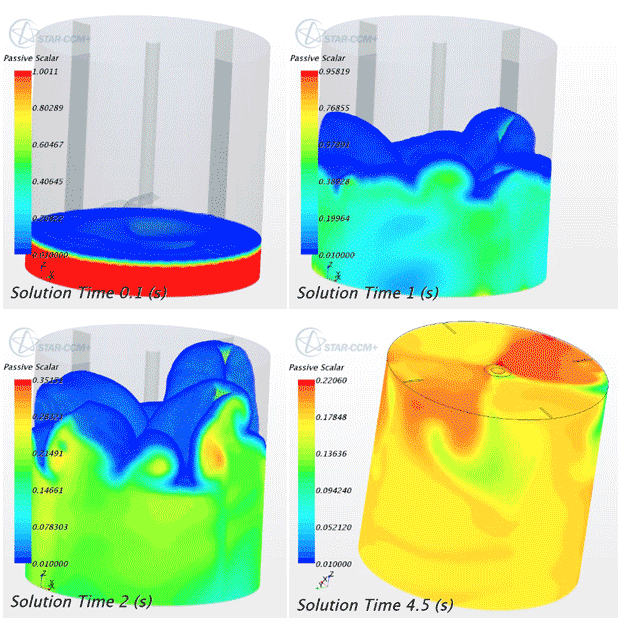
On the other hand, CFD (computational fluid dynamics) can easily address this shortcoming of data by providing the flow and concentration field in a continuum space. This makes it possible to take into account the quality of mixing at every cell inside the numerical domain, and to define a far more statistically accurate result for mixing time measurement. In this regard, STAR-CCM+ has a pre-defined equation for measuring the volume uniformity throughout the entire domain. Mixed liquid has been tracked as a passive scalar that is initially at rest at the bottom of the vessel (see Fig. 4, solution time 0.1 s). The passive scalar is like a numerical tracer mixed with water over time, and eventually the mixture achieves a uniform concentration throughout the whole domain. Fig. 4 illustrates the visual change in concentration of tracer over time.
However, in order to quantify the uniformity, several points inside the domain are defined and the concentration of passive scalar tracer at these points are tracked over time. The results are shown in Figure 4. For an ideal homogenous mixing, the mixing time is defined as the time required for achieving 100% uniformity at all of the tracer points (uniformity=1). In this study, achieving the 95% uniformity for all the tracers was desired and has been used as the criteria for mixing time. The mixing time measurements are summarized in Table 1.
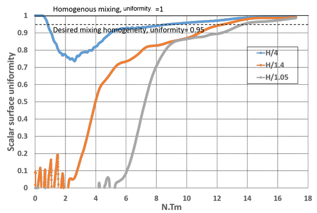 Time evolution of the passive scalar tracer concentration at different levels; dashed line on the graph indicates the desired mixing homogeneity (uniformity = 0.95).
Conclusion
Single-phase simulation of a stirred tank equipped with an HTPG4 impeller has been modeled using different computational tools. CFD simulation results with STAR-CCM+ give significantly accurate values as compared to experimental ones for the power number, the pumping number and the mixing time for a mechanically stirred tank.
Compared to other tested software, with comparable mesh element number, STAR-CCM+ gives the fastest results while maintaining the same accuracy. Also, the ease of use, hassle-free setup, and fast turnaround time for STAR-CCM+, along with various types of post processing capabilities, gives Pierre Guerin a remarkable advantage over its competitors in the market. This has given the company the confidence to use STAR-CCM+ for its future simulations.
References[1] G.L. Lane & P.T.L. Koh: CFD simulation of a Rushton turbine in a baffled tank. International conference on CFD in mineral & metal processing and power generation CSIRO, 1997.
[2] E.L. Paul, V.A. Atiemo-Obeng & S.M. Kresta: Handbook of industrial mixing, Wiley-Interscience Publ., 2004.
Subscribe to our FREE magazine, FREE email newsletters or both!
Latest News


