Success from Lab to Fab
To provide manufacturers with reliable information, test instruments for both R&D and production need to be fast, accurate, and flexible.


August 1, 2004
By Andy Armulat


Figure 1. I-V data, such as those used to plot this transistor curve family, are fundamental measurements in many labs and production facilities.
Figure 1. I-V data, such as those used to plot this transistor curve family, are fundamental measurements in many labs and production facilities.
It seems logical then that the same equipment should be used in both locations. The tricky part is picking the instrumentation that can handle both jobs. To ensure that measurement equipment performs well in both the development and production theaters, several criteria should be considered. These include the number of measurement points required on the DUT (device under test), sensitivity, repeatability, speed, programmable features, and data-handling capabilities.
I-V Data CollectionIn both R&D and production, I-V curves are used to characterize devices and materials through DC source-measure testing. These applications might also require calculating the resistance and the derivation of other parameters based on I-V measurements. For example, I-V data can be used to study anomalies, locate maximum or minimum curve slopes, and perform reliability analyses. A typical application could be finding a semiconductor diode’s reverse bias leakage current and doing forward and reverse bias voltage sweeps and current measurements to generate its I-V curve. (see Figure 1, above right)
In the past, these tests were often performed with a dedicated curve tracer, which is essentially an oscilloscope with built-in DC source for applying voltage or current to the DUT. Unfortunately, many curve tracers have become obsolete, and those still available range in price from $15,000 to $30,000 or more. And most of them are incompatible with modern computer communication buses, requiring manual setup and operation, and might require that data be exported only to floppy disks. 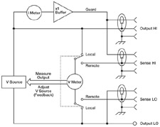
Figure 2. Four-wire (Kelvin) connections using remote sense terminals reduce error due to voltage drop in test leads. To reduce leakage current errors, the SMU’s guard buffer can be used; it creates a low impedance point in the circuit that is nearly the same potential to be guarded as the high impedance point. The guard sense lead detects the potential at that point.
An alternative could involve combining PC-connected instruments, such as a voltage or current source and digital multimeter (DMM) or picoammeter. This approach, however, requires significant effort to program each instrument, properly connect signal and triggering cables, and resolve timing issues.
Yet another alternative uses integrated source-measure instruments to cut equipment costs and make it easier to generate I-V curves. These high-precision instruments, like the SourceMeter instruments from Keithley Instruments, Inc., can act as either a voltage source or current source with sweep, pulse, and compliance limit capabilities, and simultaneously measure I and V parameters with high resolution.
Data Correlation ProblemsWhen a new device reaches the manufacturing stage, its performance and reliability are often tested by comparing production measurements to those taken earlier in the R&D lab. Frequently, a discrepancy in those measurements becomes a source of great frustration, and this lack of agreement can be a function of the measurement uncertainty that often arises.
In general, test instruments account for about half the uncertainty in any given data set. The other half has to do with the external test environment, ancillary hardware, and measurement techniques. If data sets come from different instruments, then their measurement uncertainty could be greater than that associated with the test environment. On the other hand, a production environment might not be controlled as well as a lab environment, and could result in more uncertainty with any given instrument.
Because of this, test engineers need to be mindful of how uncertainty or change can be introduced into measurements when going from lab to fab. And they need to answer the following questions:
• Is absolute accuracy important (traceability to national or quantum standards)? This is more likely the case in an R&D lab during early stages of development.
• Is it only important that measurements be highly repeatable (i.e., all measurements of a given quantity consistently yield the same result, regardless of the absolute value)? This is often the case in production.
• How much time can be spent on the measurement? Generally, there is a compromise between measurement speed and accuracy, and speed tends to be paramount in a production environment.
Data sets collected with different measurement techniques emphasizing different objectives will probably have different levels of precision and weak correlation. (In a group of I-V measurements, precision is defined by how well the curves match, and the degree of mismatch defines the level of uncertainty between the sets of measurements.)
This precision is most easily improved by using the same instrumentation in all test locations and then identifying and minimizing the sources of error. Typically, the fundamental limitation on resolution (the smallest signal change that can be detected) is determined by the total noise in the measurement circuit. Some of the noise is generated in the DUT, some in the interconnections, and some in the measuring instruments.
Source-Measure Instrument CriteriaThis is where SMUs (source measurement units) come in. They are designed with programmable features for cost-effective measurements in a wide range of applications. They contain four quadrant current and voltage sources controlled by a microprocessor, and some offer a pulse mode with up to 1kW amplitudes. They can source a series of voltages, measure corresponding currents, and store data in memory until the I-V sweep is completed. Data are then downloaded to the PC controller for processing.
To pick the right SMU for the job, the test engineer must look at five criteria: measurement sensitivity, accuracy and repeatability, speed, programmable hardware and firmware features, and software and data handling capability.
Keithley’s 2400 Series SourceMeters, for example, can simultaneously apply and measure voltage or current from microvolts and femtoamps up to more than 1kV or 10A. Accuracy and repeatability varies from about 0.025 percent to 0.10 percent, depending on the source and measurement ranges selected. If there is significant voltage drop in connecting leads due to high currents, accuracy can be improved with an SMU’s four-wire measurement capability (voltage measured or controlled between Sense HI and Sense LO terminals).
Some SMUs have a noise floor as low as 0.4fA p-p, and their guard circuits (see Figure 2, above right) can alleviate measurement errors due to stray leakage in cables and fixtures. High sensitivity and accuracy are especially valuable in production testing when a DUT’s reverse bias leakage current must be less than a predetermined threshold. By programming the SMU with a compliance limit below the acceptable leakage value, fast go/no-go testing is possible.
A production SMU should have features that speed up testing. These features can include a digital I/O interface that lets a user link the unit directly to a component handler for elementary control functions. A hard-wired trigger link between the SMU and other test equipment will reduce external bus traffic. Proper trigger synchronization assures adequate settling time between source application and DUT response measurements, but keeps this time to a minimum for the highest possible throughput.
Many SMUs are available with built-in automation, including source-measure sweeps and program memory (also called a source memory list) that allows storage of entire test sequences. This further reduces bus traffic, since only one or two commands need to be sent from the PC to the SMU to initiate a complex test sequence. Using the SMU’s data buffer allows measurement rates as high as 2000 readings per second. The actual rate depends on the signal integration period—also programmable to reduce AC line cycle noise from the test environment. For example, an A/D integration period of only 0.01 PLC (16.7µs at 60Hz) will provide measurement resolution of about 4 1/2 digits, and allows maximum measurement speed for production testing. Longer A/D integration periods maximize measurement resolution for the most accurate device characterization.
Finally, SMU manufacturers offer software to increase the versatility of their instruments. For example, Keithley supplies LabTracer software that can control up to four SMUs for curve tracing with several advantages over traditional curve tracers. It allows for flexible control of a diverse family of SMUs to characterize a wide range of two-, three-, and four-terminal devices. It has curve tracing channels with individually customized source and measurement parameters. LabTracer can view measurements from each channel graphically or in a spreadsheet (data can also be manipulated using complex mathematical expressions). And it provides integration of data collection, analysis, and storage without using floppy disks so data can be exported to other software programs for further analysis.
Connecting feature-rich SMUs to a PC controller means a broad range of measurement objectives can be satisfied while keeping costs down. Moreover, using SMUs in both R&D and production enables accurate measurements with a high degree of correlation, and that means hitting targets more consistently while eliminating the frustration of missed opportunities.
Andy Armutat is a BSEE with 10 years’ experience as an instrumentation design engineer and product manager at Keithley Instruments, Inc. You can contact him about this article at Desktop Engineering Feedback.
Company information
Keithley Instruments
Subscribe to our FREE magazine, FREE email newsletters or both!
About the Author
DE’s editors contribute news and new product announcements to Digital Engineering.
Press releases may be sent to them via [email protected].


