

Latest News
March 1, 2014
When you’re building something as high-stakes as an electric car and your company is as high profile as Tesla Motors, time is of the essence for getting a high-quality production vehicle out the door, especially when you’re looking to be the innovator in a pioneering market.
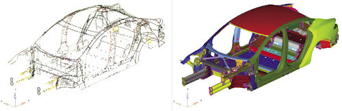 The Model S employs more than 300 fixings, including bolts, rivets, adhesives and welds. Images courtesy of Tesla Motors. |
While there was plenty of opportunity for large-scale process improvement to optimize its development cycle, the Tesla simulation team got significant mileage out of a relatively small change to its finite element analysis (FEA) model preparation procedures. By automating how it handles the connector portion of its CAE model, the simulation team was able to shave days off its design process—and redirect that time to more in-depth analysis studies.
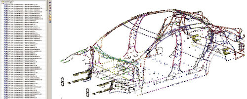 When the CAD file is imported into HyperMesh, all specification connections are contained in the component title. This information is used to fully automate the CAE connection creation. |
“The big pressure is getting the product out to the market as soon as possible and trying to improve quality,” says Singai Krishnamoorthi, technical specialist and staff engineer at Tesla. “Cutting off two to three days of the design cycle doesn’t sound like that much. But Tesla runs a tight schedule, and when you’re aiming to get a car out in one-and-a-half years, every single day counts.”
Founded in 2003 by serial entrepreneur Elon Musk—the man behind such well-known ventures as PayPal and SpaceX—Tesla’s development efforts have grabbed worldwide attention. The company’s mission is to launch mass-marketed electric vehicles designed to capture the fancy of buyers unimpressed with the quality and performance of first-generation electric car offerings.
Tesla comes at the electric car market with a three-pronged strategy. In 2006, it introduced a high-end, high performance sports car called the Roadster to establish that electric cars were viable and, more importantly, had sex appeal. Six years later, it released the Model S sedan—which, at a base price of about $50,000, was half the price of the Roadster. The third phase is to produce a mass-market, affordable electric vehicle for mainstream buyers at about a $35,000 price point. It’s a milestone that Musk recently said was still about three years away.
In the interim, the company is selling a notable number of its higher-priced models. Since the Roadster officially hit the streets in 2008, there have been more than 2,300 sold, and the automaker recently revealed that it had taken orders for 6,900 Model S sedans in the last quarter of 2013—a 25% spike over the previous quarter.
Connector Conundrum
With so much attention lavished on Tesla’s business plan and engineering efforts in the areas of sleek aerodynamic design, electric powertrain, and battery strategy, an optimization effort focused on connectors might seem rather mundane. But there are more than 300 different fixings and more than 6,000 welds points on the Model S sedan, which competes with luxury brands like BMW and Lexus. Among the different connector types are welds, bolts, rivets, adhesives and MIG welds.
When preparing a CAD model of the Model S to be meshed for simulation, the most time-consuming task is to recreate the connectors, Krishnamoorthi says. “Creating a mesh of 350 body and white panels can be done within a couple of hours using batch meshing as long as the CAD is clean,” he adds. “The bottleneck is putting everything together and making sure we’re not missing out on any spot welds, rivets or bolts.”
Tesla CAE engineers were concerned about overlooking a metal inert gas (MIG) weld or adhesive because of the way connectors were traditionally handled as part of building and updating the CAD model. While the 3D models included a representation of the various connectors, there wasn’t always enough detail in the CAD file to determine what type of connector was used, let alone any of its mechanical properties or what panels it was connecting.
| Tesla Optimizes Designs for Pedestrian ImpactAltair’s HyperStudy is finding a new role at Tesla, aiding in the design group’s efforts to meet legal pedestrian impact requirements and the New Car Assessment Program (NCAP). The NCAP test represents a pedestrian being hit by a vehicle traveling at 40 KPH with the goal being to minimize injury to the head, upper, and lower leg. The allowable injury threshold is a moving target, forcing manufacturers to come up with innovative ways—including pop-up hoods or airbags—to meet the requirements without sacrificing the vehicle’s styling. Using HyperStudy, Tesla is evaluating a range of solutions to better understand and find solutions to the problem, according to Singai Krishnamoorthi, staff engineer. “The most important thing is not to restrict the creativity of the stylist,” he explains. We’re trying to give them guidance so they can find ways of solving and still optimize the design.” While conventional wisdom puts the ideal head acceleration curve to meet the requirements to be a square pulse, giving a stop distance of 83mm for a head injury criterion (HIC) target of 650, the HyperStudy analysis helped prove otherwise. Malcolm Burges, a Tesla engineering manager, came up with a theoretical optimum curve that delivered a stop distance of 68mm, which is 22% better than the widely touted square acceleration curve. Using HyperStudy, the team was able to prove the theoretical curve was the optimum acceleration curve as opposed to the square pulse, despite the fact it is more difficult to engineer. “HyperStudy let us challenge conventional wisdom and optimize a design that was outside of conventional assumptions,” Krishnamoorthi says. “This approach was also used for the lower leg impact as well.” —B. Stackpole |
“There are a handful of ways to represent connections within a CAD file. They can take the shape of a point, line, or even a surface. When brought into a CAE environment, we can use this information to generate different types of FEM connection representations. Examples would be a bolt (line), a spot weld (point), or an adhesive (surface). All of this information in the CAD file, and we were able to read and realize those in the CAE environment with the tool we developed,”explains Ben DiMiero, applications engineer at Altair, a CAE vendor who worked with the Tesla simulation group on the CAD connector automation project.
Typically, the connector was exported as a standard text file, which specified all of the coordinates for connectors, the various types, and what specific panels it was being used to connect. It was up to the CAE engineer to use the data to manually recreate the connections in the CAE model. The process proved to be both laborious and an inefficient use of the engineer’s time.
Working with Altair’s DiMiero, the Tesla simulation team decided that a more effective approach was to keep all of the detailed connector in the CAD file, which in Tesla’s case was Dassault Systemes’ CATIA. Tesla’s Cory Ostrow led the effort to create a connector (CNX) CAD structure, putting tags on the connector entities to maintain consistency in naming and tree structure so the data could easily be extracted with a search string. Paul Hamrick created the CNX data merge tool, which creates an Excel file that depicts such CATIA geometric entities as where they reside in the overall CATIA tree as well as the connection type, among other attributes. Jenny Wu created an Excel macro that is used to mark all relevant geometric entities in the Excel spreadsheet that need to be exported in one sweep, based on the search string given by the design engineer. The last piece was a HyperMesh TCL script, which imports the updated CATIA files created by the CNX Data Merge tool into HyperMesh. The Tcl script also creates all the CAE connection elements for the various weld types, and highlights which connectors failed to be created.
The end result eliminated the manual labor and reduced the model creation process by a couple of days. Typically, all body in white pressed panels can be batch meshed in a half-day, but the connections can take as long as two to three days, Krishnamoorthi explains. This becomes a significant time saver because the analysis team frequently recreates the CAE model in response to design changes.
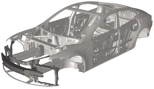 A body in white CAD model of the Tesla Model S. |
“Because we have to respond to design changes very quickly, we can’t say, ‘give us a few weeks to build a model,’” he says. “We actually wanted to give people an answer in a very short time.”
While the actual development of the scripts and macros was straightforward, the bigger challenge was coming up with a solution that didn’t drastically affect how engineers worked with CATIA or HyperMesh, Krishnamoorthi says: “We didn’t want to tell the CAD users they were going to have to spend an extra 20 minutes modifying the way they worked. We had to come up with a process that would have the least amount of impact, yet was very robust and not prone to mistakes and errors.”
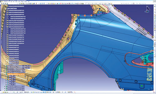 To facilitate automation, the team created a CNX CAD structure using consistent naming and a tree structure to ensure the relevant connector data could be extracted. |
For example, Tesla design engineers had historically used random names to define a weld or a connector type in the CAD file. Once the connector automation program was launched, the engineers were instructed to use a specific set of terms, so the scripts could filter out what was needed to create the actual connections in the model. “One designer might specify something as a ‘MIG weld line’; another might call it a ‘MIG weld curve’; and yet another might just specify ‘curve,’” Krishnamoorthi offers as an example. “We asked them to stay consistent with naming and where the data is placed in CATIA. That way, we can extract it very efficiently.”
While the HyperMesh script has certainly made a dent in the CAE model creation process, the more important benefit of the automation initiative has been redirecting that time to allow the Tesla CAE engineers to do more in-depth analysis.
“Because we saved time building the model, we could spend more time looking at the results and making sure the designs were optimized,” Krishnamoorthi concludes.
Beth Stackpole is a contributing editor to DE. You can reach her at [email protected].
More Info
Subscribe to our FREE magazine, FREE email newsletters or both!
Latest News
About the Author
Beth Stackpole is a contributing editor to Digital Engineering. Send e-mail about this article to [email protected].
Follow DE

