
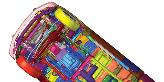
Meshes were created using ANSYS Mosaic-enabled Poly-Hexcore meshing that automatically combines disparate meshes with polyhedral elements for fast, accurate flow resolution. ANSYS Fluent provides Mosaic-enabled meshing as part of a single-window, task-based workflow. Image courtesy of Sheffield Hallam University, Centre for Sports Engineering Research; and ANSYS.


Latest News
November 1, 2018
Are you the type who likes to take a peek inside the black box to see how it works? Or are you one who’s willing to put your faith in the black box? The answer to that may offer clues to the type of meshing applications that appeal to you. But that’s not the only factor. Your own finite element analysis (FEA) skills also play a role.
Most simulation programs aimed at design engineers offer fully or almost fully automated meshing. In other words, the software makes most or all of the mesh-related decisions required. Your part may be limited to selecting the desired resolution or the level of details—fine meshing (high resolution, takes more time, but more accurate) or coarse meshing (low resolution, takes less time, but more approximations involved).
Numerous options are available in Altair HyperMesh to manage complex assemblies. Image courtesy of Altair.
There are good reasons to keep the meshing process hidden inside the black box, as it were. It takes a lot of experience and expertise (perhaps even a Ph.D.) to understand the difference between, say, a hexahedral mesh and a tetrahedral mesh; or tri elements and quad elements. It takes considerable simulation runs to know what type of meshing methods work well for a particular set of solid geometry. It requires yet another level of wisdom to know how to manually readjust the software-generated meshes to more accurately account for the problematic curvatures, corners and joints in your geometry. These are beyond the scope of what most design engineers do. Therefore, many argue presenting a design engineer with a menu of these choices is counterproductive.
On the other hand, expert users with a lot of analysis experience know the correlations between mesh types and accuracy, so they may want to get more involved in the meshing process. For this reason, high-end analysis software usually offers much more knobs and dials in the meshing process. Depriving expert users of these choices would force them to accept what they know to be unacceptable approximations. To navigate between the two different approaches, you need at least some understanding of how meshing works, automated or manual.
Good Mesh Equals Good Results
Abdullah Karimi, CFD analyst for Southland Industries, uses fluid dynamics programs to examine airflow and heat distribution to develop the best residential heating solutions for his company’s clients. In The Big Room, an online blog by Southland Industries, Karimi penned an article titled “How Not to Mesh Up: Six Mistakes to Avoid When Generating CFD Grids” (http://inthebigroom.com, November 2017). His first tip: Never use the first iteration of automatically generated mesh.
“I’ve realized even some people with Ph.D.s don’t have a good grasp on meshing,” he says. “People say, garbage in, garbage out. I say, good mesh equals good results. But the vast majority of the times I’ve seen the [software’s] automatically generated initial mesh is too coarse. The mesh may not even work, and if it does, the result may not be accurate.”
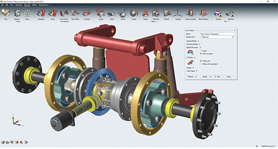
In contrast to Altair HyperMesh, Altair Inspire lets users tune analysis parameters without even seeing the mesh. Image courtesy of Altair.
If the automatically generated mesh significantly distorts the original geometry’s prominent characteristics—such as rounded corners, sharp angles and smooth curves—it may be a sign that the mesh needs manual intervention in those specific regions.
“You should at least take a look at the mesh. You can check to see if there are sudden size transitions, aspect ratio for skewness and triangular distortions. Just by visually inspecting the mesh, you can get a good idea if this may or may not work for your problem,” says Karimi.
In his article, Karimi advises, “Don’t hit ‘Run’ without a mesh quality inspection ... Depending on the robustness of the solution scheme, this could cause serious issues like straightaway divergence of the solution ... There are several quality metrics that need attention depending on mesh type and flow problem. Some of these metrics include skewness, aspect ratio, orthogonality [and] negative volume.”
The Mesh Types
With its designer-friendly Altair Inspire (previously solidThinking Inspire) and expert-centric Altair HyperMesh software, Altair offers different approaches to meshing.
“In Inspire, meshing is mostly hidden from the user,” explains Paul Eder, senior director of HyperWorks shell meshing, CAD and geometry at Altair. “The users choose to solve either in the first order [which prioritizes speed] or second order [which prioritizes accuracy].” By contrast, in HyperMesh, “We expose a lot more knobs and dials, because it’s for advanced users who understand the type of meshes they want to generate,” he adds.
A similar strategy is seen in ANSYS software offerings. “Two of our products, ANSYS Forte and Discovery Live, provide a fully automated meshing experience,” says Bill Kulp, lead product marketing manager for Fluids at ANSYS. “ANSYS Discovery Live provides instantaneous 3D simulation so there is no time to make a mesh. On the other hand, our [general-purpose CFD package] ANSYS Fluent users need to solve a wide variety of fluid flow problems that can be most accurately approached by optimizing the mesh for the task at hand.”
“Push-button automated meshing is our goal because we want to take this time-consuming job away from the engineers so they can concentrate on the innovation and optimization of their products,” adds Andy Wade, lead application engineer at ANSYS. “Automated meshing will enable AI and digital twins to run simulations in the future and so this area is becoming the focus.”
In theory, design engineers and simulation analysts could use different products, but in reality, some design engineers have sufficient expertise to make critical meshing decisions; and some analysis experts prefer the efficiency of automated or semi-automated meshing. So even with different products, satisfying both crowds is a difficult balancing act for vendors.
Though the meshing process is mostly kept in the background in Altair Inspire, “If you’re an advanced user and want to see the meshes, you have the option to,” says Eder. “At the same time, we also offer automation in HyperMesh, because even some expert users want the same ease of use seen in Inspire.”
“Tools such as ANSYS Discovery Live takes the meshing away completely from the user, whereas Discovery AIM features automatic physics-aware meshing, so the user can allow the product to do the hard work but if they want to see the mesh and tweak it they can take control,” says Wade.
Regional Meshing
The relatively new startup OnScale recently began offering on-demand multiphysics simulation from the browser. Some firms like Rescale offer high-performance computing (HPC) resources needed to run simulation, but not the software. By contrast, OnScale offers both the hardware and the multiphysics solver required to process jobs.
“We offer automatic meshing as well as user-defined meshing. Users can define the level of fidelity desired,” explains Gerald Harvey, OnScale’s founder and VP of engineering. “OnScale gives you the ability to refine the grid and apply finer meshes in specific regions.”
Not every corner, section or region in your geometry needs fine meshing. With simple geometry, a coarse mesh with fewer elements may suffice. But in certain regions where curvature, contact and joints create complex stress concentrations or flow patterns, a finer mesh (simply put, a higher number of meshes to cover the area) is warranted. Advanced simulation programs usually offer tools to specify how to treat these regions. Even in programs that target design engineers, some tools may be available to treat these regions differently.
“In Altair FEA products like SimLab, you can perform automatic local mesh refinement,” says Eder. “So you can run an analysis, review the results, then automatically refine the mesh in areas of high strain energy error density for subsequent runs. In [expert-targeted] HyperMesh, you also have many more manual mesh refinement options.”
Simulation Cost
OnScale’s Harvey suggests running a mesh study to understand the correlation between the stress effects and the mesh types and mesh density chosen. This can offer clues on how meshing affects the FEA results.
“Every engineer should conduct a mesh convergence study—test the meshes with some key performance indicators (KPIs) to find a happy medium,” says Harvey. “Suppose you’re looking at the design of a bracket. Then look at how the different meshes affect the bend angle of the bracket, for example.”
Calculating simulation cost is complex, in part due to the mix of licensing policies in the market. But fundamentally, two parameters are involved: the time it takes and the hardware it uses. The need to find simplified meshes (as simple as possible without infringing on the accuracy of results) largely stems from the desire to keep these two parameters as low as possible.
“If you have a simple solid part and you put 3D meshes on it, it takes more times than necessary to run,” notes Eder. In such a case, running simulation in a 2D cross-section of the geometry may be much more efficient. “And think of how many iterations you plan to run, because you’ll be paying that penalty for every single run,” he adds.
ANSYS’ Wade points out that most solvers prefer hexahedral elements or quad surface mesh because “they fill the space very efficiently and using such elements when transient or explicit analysis is required can give massive gains in solve times (minimizing CPU effort for calculations). Hex elements can follow the flow direction better as well, which has some accuracy benefits. Tetrahedra, polys and other unstructured methods are very popular because they don’t require the decomposition (chopping up) of the space like a hex mesh; as a result, they are excellent for automation and really minimize manual effort.”
Another tip from Karimi’s article: “Don’t fill the domain with a ridiculous number of tetrahedrons ... So many times, I see meshing engineers filling up their CFD [computational fluid dynamics] domains [the target region for fluid analysis] with a large number of tetrahedrons and then struggling to get simulation results on time.”
Certain programs are equipped to make the mesh selection easier. “With OnScale, you can conduct a study on a sweep of design, with mesh being one of the variables,” Harvey points out. “In OnScale, the run wouldn’t cost you significantly, because it would be a one-off cost. And the payback is well worth it.”
Physics vs. Mesh
Choosing the right kind of mesh, applying the right density to critical regions and selecting the right kind of coarseness or looseness affect the accuracy and speed of the simulation job. That is an exercise in tradeoffs, so there’s no black-and-white answer.
“Meshing is always an exercise in tradeoffs in the quality of the mesh versus the speed of the solution,” says Karimi.
“If you just want to see if a part will stand up to stresses and daily beating over time, and you’re not looking at the lowest level of details but at a high level of generality, then getting your physics correct is more important than the mesh,” says Eder.
That means, at the general concept design level, the loads and boundary conditions—such as temperature, forces and direction of the forces—may be more important than the type of meshes selected.
Subscribe to our FREE magazine, FREE email newsletters or both!
Latest News
About the Author
Kenneth Wong is Digital Engineering’s resident blogger and senior editor. Email him at [email protected] or share your thoughts on this article at digitaleng.news/facebook.
Follow DE

