

Latest News
December 1, 2013
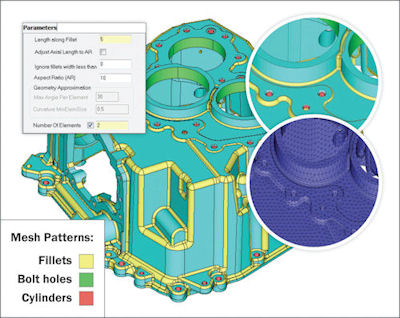 With Altair’s software, you can automatically single out the minor features that fall within a range to decide whether they should be disregarded in the simulation. Image courtesy of Altair. |
Wrong, according to H. Clark Briggs, Ph.D., from ATA Engineering Inc. ATA supplies design analysis and testing services to major manufacturers. Briggs, vice president of aerospace and defense business development, estimates his staff spends between 30% and 50% of the project time repairing their clients’ geometry.
Indrakanti Chakravarthy, Siemens PLM Software’s director of simulation marketing for the Americas, has a higher estimate: “Up to 70% of an analyst’s time is spent searching for data and preparing a model for analysis.”
But what’s the cure: simulation-led design or adopting a standardized design toolset for both CAD and CAE?
Design-led vs. Analysis-driven Workflow
“The current workflow is so bad. While it’s very common, it’s horribly wasteful—and I fought for the last 20 years for companies to realize it,” Briggs laments. “I spend most of my process consulting time trying to get organizations to realize it.”
In the current product development roadmap, simulation and analysis experts typically receive 3D geometry constructed in mechanical design programs by design engineers, often in a finalized, fully detailed form. Because the typical design department is less knowledgeable about digital simulation, CAE software users often have to repair or refine the 3D model before they can run a simulation.
Some advocate reversing the process: Let simulation and analysis define the initial design’s shape. Briggs, however, is more cautious. He recommends a workflow in which “the evolving design is regularly and actively shaped by inputs derived from performance analyses.” He also recommends working in a toolset that accommodates both design and analysis—in ATA’s case, NX—to reduce data exchange headaches.
Analyze or Optimize?
Previously, the CAE software users’ prep work primarily consisted of identifying and (in most cases) removing features too small to make a difference in simulation. Today, the rise of computer-driven optimization adds a new twist.
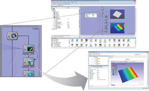 With Phoenix Integration, users can iteratively run analyses and then automatically upload results into PHX AnalysisLibrary for data capture. Image courtesy of Phoenix Integration. |
Analysis involves subjecting a 3D digital replica of your product to simulated loads and stresses to predict how it would perform under real-world usage. A typical analysis might be something like simulating the drop of a cellphone at a specific height and angle to determine whether it can withstand such an accident.
By comparison, topology optimization, a more recent practice made possible by increased computing power, uses sophisticated algorithms to seek the best possible shape or parameters for a product. For example, it might be used to identify the leanest airplane wing based on manufacturing material properties and anticipated loads.
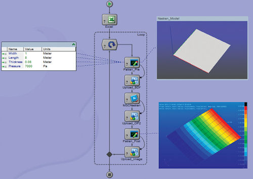 Automating the data exchange between CAD to CAE is part of Phoenix Integration’s service offerings. Shown here is the analysis view in PHX ModelCenter. Image courtesy of Phoenix Integration. |
In the past, a team of experts would have reviewed the results from digital simulations to determine how to refine the original design. With optimization, the computer steps in to do the lion’s share of the job human experts once did. The algorithm-driven method can also provide designers and engineers with unconventional solutions seldom explored if executed manually.
| Things CAD Users Can Do to Make CAE Users’ Life Easier HClark Briggs, Ph.D., from ATA Engineering Inc., a design analysis and testing service provider, shares the Top 3 CAD practices that add work in subsequent CAE studies. 1. Don’t add dependent features to a feature that the CAE user may need to remove (for example, as the child of a blend). Whenever possible, keep such minor features at the edge of the feature tree so they can easily be removed without affecting the core geometry. 2. All separate bodies should be at the part level. Briggs admits that this may depend on the organization’s preference, as some firms do use—and many CAD software supports—building multi-body parts. 3. Give the analysts an easy way to find material More Information. Usually it’s embedded in the CAD model so CAE software can automatically picks it up. If it’s not, the CAE users need to know how to find it. —K.W |
“The key in developing the geometry parameters for optimization is to control the design space,” notes David Vaughn, simulation software maker CD-adapco’s vice president of worldwide marketing.
For instance, if you plan to run an optimization study on the best possible shape for an airfoil, he says, the key is to limit the shape parameterization to feasible airfoil shapes. If you put a bunch of non-uniform rational basis spline (NURBS) control points into the mix, you’ll end up with possibly hundreds of variables. That’s overdesigning for optimization, Vaughn says, “because the objective is to minimize the number of simulations required to get to the optimal answer.”
S. Ravi Shankar, Ph.D., Siemens PLM Software’s global director of simulation product marketing, agrees: “If you start out with geometry that’s too detailed, if you were to mesh that without any simplification, if would be a large mesh model. Then each iteration would take much longer.”
Considering the number of variations the computer would need to generate before arriving at the answer, the computing time could increase exponentially, Shankar adds.
Defeaturing Makes Way for Shrink-wrapping
Several direct-editing programs also serve the CAD-to-CAE data exchange. Without the restrictions and learning curve of history-based CAD, these programs were able to capture a portion of the analysts looking for an easy way to edit 3D geometry. (Editor’s Note: For more, read “Direct Modelers as FEA Pre-Processors,” Part I & II, April and May 2012.) But the CAE vendors soon struck back, by introducing their own geometry cleanup functions and tools.
“I’m sure ]direct modelers] help,” says Simone Bonino, Altair’s marketing director for HyperWorks. “But the question is, do you really need another tool between CAD and CAE? Now, you can skip that step.”
One of the shortcuts is known as shrink-wrapping or surface-wrapping, a method that’s quickly becoming the standard approach in dealing with pesky features. Another is the automatic detection of features.
CD-adapco’s Vaughn says, “The feature that we pioneered for that purpose is surface wrapping.” The tool lets CAE users shrink-wrap imperfect CAD geometry to prevent holes, gaps and overlapped surfaces from compromising the analysis. “The benefit of that is, you can use the most complex CAD model you’ve got for optimization and can still mesh it very quickly—and it’s automated,” he adds.
Siemens’ Shankar points out that NX also has a surface-wrapping tool. “For example, if you’re trying to study the cooling under the hood of a car, you’ll need to specify the flow volume,” he says, referring to the enclosed space under the hood with the mechanical components excluded. “We have tools that let you create that volume based on the solid models you have. In the past, that volume could only be defined in the preset global resolution. In NX 9, you now have the option to specify a finer resolution in certain regions to capture necessary detail.”
Altair HyperWorks CAE suite takes a similar approach with its shrink-wrap feature, described as a way “to generate an enclosed volume or solid mesh, and is typically used to approximate and simplify an existing model.” With the option to specify whether you want a loose or tight wrapping, you can speedily create the general shape of the geometry with the desired mesh resolution.
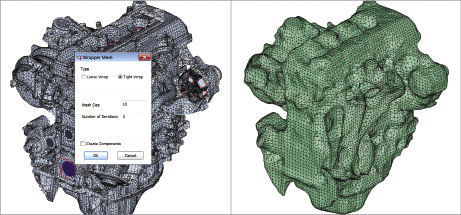 In Altair’s software, you have to option to shrink-wrap a complex model. The dialog box lets you choose a tight wrap or a loose wrap. Image courtesy of Altair. |
Another alternative comes from Altair’s SimLab (acquired by Altair in 2010). Ulrich Gollwitzer, Altair’s marketing manager for modeling and visualization products, notes that SimLab “reads native geometry, along with the CAD parameters. It specializes in solid-meshing technology—for example, powertrain and ]computational fluid dynamics, or CFD] applications. The software can automatically recognize parametric features. But in SimLab, instead of simplifying the geometry, you identify regions and set local or global mesh parameters.”
Once the software has identified features that are problem-prone in simulation, SimLab offers you the choice to disregard them, or treat them a certain way during meshing. If you have gone through this process, you can save the treatment as a template, so SimLab knows how to address future CAD geometry that involves the same type of features—for instance, using a specific mesh pattern for holes in-between certain ranges.
What’s Important? Who’s Asking?
| Mid-surface Extraction In some cases, the simulation job can be reduced from 3D to 2D calculations through the use of mid-surfaces, or the use of 2D cross-sections to represent 3D geometry. The use of 2D planes reduces the meshing and solving times dramatically. Many CAD and CAE software today lets you automatically extract mid-surfaces from solid geometry. —K.W. |
As president and CEO of the multi-disciplinary optimization specialist Phoenix Integration, Scott Woyak, Ph.D., has seen both sides of the design-simulation division. Phoenix Integration’s expertise is workflow automation, including the common CAD-to-simulation workflow. Sometimes the project involves custom application programming interface (API) development.
“We’ve seen some customers who develop their own system to clean up CAD geometry for optimization,” Woyak says. “Some use specialized tools like Sculptor ]from Optimal Solutions Software].”
Sculptor lets you deform and adjust your mesh models in optimization runs. It uses what the company describes as “Arbitrary Shape Deformation (ASD) technology and can be linked to existing fluid-flow (CFD) and/or structural (FEA) analysis tools to accelerate CAE design optimization efforts.”
The key to eliminating the wrinkles in CAD-to-simulation is to figure out “the best way to construct your geometry so you won’t encounter problems in simulation when you try to solve,” says Woyak.
The discussion, therefore, raises a question: Is it fair to put the burden on the designer?
Reshuffling the Order
“People are beginning to realize that, to lower cost and shorten cycles, they’ve got to use simulation more, earlier in the process,” Woyak observes. “When we work with a customer, we try to explain to them about these geometry-related issues and guide them toward simulation-driven design.”
ATA’s Briggs says he’s a “big fan of putting the whole organization on a homogenous toolset. I guarantee that you’ll make one-and-a-half or two times’ improvement in productivity and in reducing technical errors.”
Gollwitzer asserts that Altair is preaching simulation-led design. “If you start out with optimization, it might even give you a completely new idea of how your structure should look like,” he adds. “Then you’re not just replicating similar design patterns over and over again.”
Gollwitzer suggests that it would be “smart to establish a workflow where the designers hand over the geometry at the level of details sufficient for an analysis. Once simulation has proven that the design works, designers can add additional details to that design. It would take a little bit of education.”
Either way, the design process is iterative, so CAD to CAE or CAE to CAD will always require communication and collaboration.
Kenneth Wong is Desktop Engineering’s resident blogger and senior editor. Email him at [email protected] or share your thoughts on this article at deskeng.com/facebook.
More Info
Subscribe to our FREE magazine, FREE email newsletters or both!
Latest News
About the Author
Kenneth Wong is Digital Engineering’s resident blogger and senior editor. Email him at [email protected] or share your thoughts on this article at digitaleng.news/facebook.
Follow DE

