
SIMSOLID, which champions meshless simulation, says its approach is well-suited for analyzing complex structures such as bones and lattice structures. Images courtesy of SIMSOLID.
March 1, 2018
Interoperability discussions tend to revolve around formats: Can your CAD program read native AutoCAD files? Does it support DWG? Does it support OBJ, STEP or IGES? And the list goes on.
In some ways, the focus on formats is understandable. For a long time, AutoCAD was—and some would say still is—the de facto standard in engineering drawing; therefore, the ability to read and edit AutoCAD and DWG files is crucial to those working with old construction documents and shop drawings. Because the majority of 3D printing hardware and the associated print preparation software work with STL, those who want to explore additive manufacturing for mass production are inclined to favor modeling programs that can export STL files.
But perhaps it’s time to take a closer look at what happens to the original CAD file’s precision geometry when it’s converted to mesh models for simulation or 3D printing. Finding new and more efficient ways to address the transitions in modeling, simulation and manufacturing may be the key to unlock more sophisticated operations, such as meshless simulation, topology optimization and lattice-driven lightweighting.
Assemble Your FE Model for Machines
About five years ago, with support from Germany’s Federal Ministry of Economics and Technology, a group of researchers from The Institute for Control Engineering of Machine Tools (ISW, Stuttgart, Germany) decided to spin off their efforts into a startup, dubbed Meshparts.
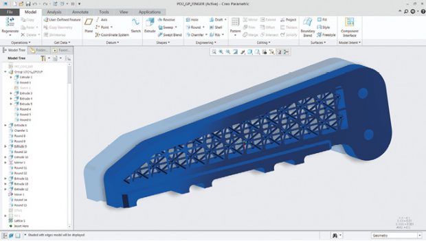 Mainstream CAD packages look for ways to faithfully model and represent complex lattice-filled parts. Shown here is a PTC Creo Parametric part with lattice structures. Image courtesy of PTC.
“In the future, all FE simulation models of machines, just like real machines, should be assembled from individual finished simulation models of individual components,” says Meshparts Founder Alexandru Dadalau, an alumni of the Mechatronics Faculty of the University of Stuttgart and a former research assistant and Ph.D. at the ISW. “The component-oriented and fully parametric FE modeling is a fully new approach in the machine simulation.”
The centerpiece of the company’s product is the FE Model Kit, a library with a “wide variety of typical machine components” delivered “as fully parametric ANSYS FE models.” The kit’s content includes standard and manufacturer-specific components.
This means Meshparts software users could assemble a FE model with standard machine parts from the kit, instead of importing a CAD assembly and converting it into a mesh model. Meshparts can also read-in non-standard machine parts and convert them to ANSYS or Abaqus format to be consistent with the rest, according to Dadalau. Furthermore: “Meshparts can read a complete assembly structure from CAD and mirror this structure into its own FE assembly structure. Then you can add predefined parametric assemblies or parts from the model kit to this FE assembly,” Dadalau explains.
Support for the ANSYS format makes sense, as ANSYS is recognized as an industry leader. However, the appeal of Meshparts’ component-oriented method will likely increase when the assembly kit’s content is available in a much wider variety of FE formats.
“We will soon release new library parts based on GMSH scripting and meshing technology,” Dadalau adds. “But Meshparts is, from the architectural point of view, not limited to ANSYS or GMSH when it comes to developing new model libraries. It’s just that we currently focus on ANSYS and newly on GMSH. We do hope that in the near future we will have a community of people developing new libraries for common use.”
Don’t Mesh Your CAD
To put a detailed CAD model through simulation, you have to simplify it and mesh it. The two-pronged approach—removing unnecessary details and subdividing the model into hundreds, thousands or even millions of tiny geometric elements for force, stress and load calculation—is fairly standard in preprocessing software. But the method is also compute- and memory-intensive.
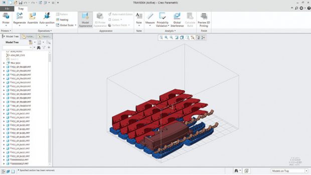 Automatic orientation and positioning of parts to be printed in the printer chamber for efficiency is a desired feature for designers exploring additive manufacturing. Shown here is PTC Creo’s deployment of this feature. Image courtesy of PTC.
One new simulation program, SIMSOLID, uses what’s known as meshless simulation, allowing users to bypass arguably the most burdensome parts of preprocessing. According to SIMSOLID, its technology “eliminates geometry simplification and meshing, the two most time-consuming, expertise-extensive and error-prone tasks done in traditional FEA.”
As the new year began, SIMSOLID announced the launch of SIMSOLID Professional. “The Professional edition extends the SIMSOLID feature set to include more CAD connectivity to applications such as CATIA, NX, PTC/Creo and Inventor, transient dynamic analysis and weld connection automation,” the company writes.
Ken Welch, founder and CEO of SIMSOLID, used to complain about the “dirty CAD geometry” that makes simulation difficult—the misaligned geometry, gaps that need to be closed and so on. But not anymore. He’s come to accept that, as part of the exploratory conceptual phase, CAD users are bound to move parts around, reorient them and deform geometry many times through different design iterations. Thus, the so-called dirty geometry may be the inevitable outcome of conceptual design; it may be unfair to ask design engineers to put in additional time to clean up or simplify the data before submitting it to simulation.
“SIMSOLID reads in the native CAD data as faceted topology,” Welch says. “Others talk about tools to simplify CAD, create mid-planes and defeature. Our approach is, just use your CAD geometry as is for the best simulation results. With this approach, we can solve large assemblies with hundreds to thousands of parts in minutes instead of hours or days.”
Task-Specific Extensions
Jose Coronado, PTC’s product manager for Creo manufacturing and simulation, finds it difficult to talk about file formats because the different Creo applications (such as simulations and additive manufacturing extensions) access a single Creo file to execute their operations. “We keep all the data needed (for modeling, simulation, additive etc.) in Creo. This removes the need to constantly recreate models in CAD or to do any file transfer between applications,” he says.
Most CAD programs employ one of a handful of geometry modeling kernels as the foundation for their modeling techniques. Dig into one of the mainstream mechanical CAD modelers and you’ll likely come across the Parasolid kernel, owned by Siemens, or the ACIS kernel, owned by Dassault Systèmes.
Some CAD vendors developed and used their own proprietary kernels, which appear in their own products and their development partners’ offerings. For instance, Autodesk once licensed its kernel, but now uses its proprietary ShapeManager kernel in Autodesk Inventor and AutoCAD software. PTC uses its proprietary Creo kernel for the PTC Creo product line.
“Most FEA programs use the H-element meshing technology. Creo Simulate uses the P-element technology and auto-meshing. This eliminates the need to understand element types. [The software] automatically creates the mesh model and accurately captures geometry contours. Additionally, the mesh is automatically refined during the solving process,” says Coronado. “It’s one of the distinctive characteristics and advantages of Creo Simulate.”
The close integration between Creo Parametric and Creo Simulate allows the adaptive mesh refinement and automatic convergence. Therefore, users with limited expertise in complex simulation can, for example, bypass the need to manually define the type of mesh to apply to certain zones in the geometry—a skill that’s common among simulation experts but rare among novices and design engineers.
The Burden of Lightweighting
In many manufacturing firms, lattice structures have become the ideal solution for lightweighting parts. Because they use much less materials than solid parts, such structures are attractive to those seeking to reduce weight in automotive and aerospace components. But due to their structural and geometric complexity, they can also put a heavy burden on simulation.
With Creo, users can use the simulation results and the embedded solver to drive automatic lattice creation, with control on the part’s stiffness to achieve the desired performance.
“With Creo, the time savings comes from the usage of idealizations by the solver. We tell the solver to use idealizations, like beams, shells and masses. That’s much faster than solving full, detailed mesh geometry—in some cases, it can be in minutes instead of hours,” explains Coronado. “What we propose to our customer is: They should run their initial simulations with simplified geometry, then when they get close to the final design, run with detailed geometry in H-elements.”
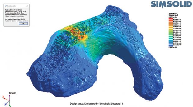 SIMSOLID, which champions meshless simulation, says its approach is well-suited for analyzing complex structures such as bones and lattice structures. Images courtesy of SIMSOLID.
Most of the time, lattice structures also prove challenging or impossible to manufacture in traditional methods due to geometry complexity. Metal-based 3D printers offer one alternative to make lattice-filled parts. For additive manufacturing applications, “the level of implementation is such that, when you hit print in Creo, the STL conversion happens automatically. And you don’t have to worry about support structures. The printer driver automatically takes care of that,” says Coronado. “This automatic creation of support structures is not for all printers, but only for the printers that support this integration.”
Printer-Aware CAD
Joe Dunne, developer relations manager for the cloud-hosted CAD program Onshape, believes being part of the cloud software ecosystem makes direct integration possible with other cloud services. “With a cloud app, you can quickly see how a change in CAD might affect the 3D printing process—in the support structures it needs, for instance,” he says.
The company’s strategy is to concentrate on browser-based parametric CAD modeling. It relies on partners such as SIMSOLID (meshless simulation), Simwise 4D (rigid body dynamics and assembly simulation) and SimScale (cloud-hosted simulation) to augment its CAD program with simulation applications. Similarly, it relies on Kiri:Moto, x3D-Print and others to supply additive manufacturing functions to Onshape users.
In his view, it makes more sense to leave the 3D print preparation software in the hands of the hardware makers, because they possess the intimate knowledge about their own machines’ eccentricities and capabilities. “The overhangs, the support structures—they are so unique to each printer or printing platform that printer companies are much better at solving these issues with their own software,” he notes. “Where we could get involved is, for instance, taking an assembly and arranging it in an optimized volume so you can print them efficiently. That’s something a CAD system should do.”
In PTC Creo’s AM extension, once the CAD program is connected to the printer, the CAD program becomes aware (so to speak) of the printer’s capability—color options, material options, build envelope size, recommended orientation for best printing and others. “Then, Creo can use the printer’s own algorithm—not PTC’s generic method—to suggest the optimal way to stack up the parts for best printing,” says Coronado.
Where exactly should the CAD program intervene, and where should it cede control to the printer’s firmware? The issue may be up for debate as more and more CAD vendors add AM-friendly features.
Lattice Can Fill Up Your Memory
An area where Onshape’s Dunne feels CAD developers should start looking for alternatives is lattice modeling. “We’ll have to figure out a way that’s different from how we currently represent lattice structures,” he says. “Even if you just have a simple bracket, if you were to add lattice structures inside it to optimize it for weight, you could easily get to a gigabyte file to represent that model, because there [are] so much details in it. So even if the CAD system can create it, the printer software might not be able to slice the file—it might run out of memory. In my view, we need to find a way to represent the lattices without modeling all the details in triangles.”
SIMSOLID is a partner of nTopology, makers of the nTopology Element and Element Pro software for generative design. nTopology offers, among other things, detailed lattice structure modeling. “Lattice analysis with traditional finite element analysis methods is difficult,” SIMSOLID’s Welch says. “We’re orders of magnitude more efficient in analyzing lattices, both in memory use and in time required. When we once worked with an nTopology assembly with lattice-filled parts, we finished it in about four and a half minutes.”
Interoperability used to mean the ability to read a comprehensive list of neutral and proprietary 3D formats—the longer the list, the better. Support at the file format level worked well when CAD, simulation and manufacturing were treated as separate parts of the product design workflow. Now that many CAD users are looking to conduct simulation upfront in the conceptual phase and identify potential manufacturing issues in their geometry, that means that interoperability discussion, too, must evolve to address the metamorphosis of the data itself.
For the new generation of engineering teams that believe in collaborative workflows, the ability to easily reuse the rich CAD data in simulation apps without too much preparatory works, and the ability to visualize and simulate how their parts might be manufactured or printed, may be much more important than the length of the file formats supported by a certain program.
More Info
Subscribe to our FREE magazine, FREE email newsletters or both!
About the Author
Kenneth Wong is Digital Engineering’s resident blogger and senior editor. Email him at [email protected] or share your thoughts on this article at digitaleng.news/facebook.
Follow DE

