
Fig. 2: Validation uncertainty as described by the LANL.


Latest News
March 1, 2015
Editor’s Note: Tony Abbey teaches live NAFEMS FEA classes in the US, Europe and Asia. He also teaches NAFEMS e-learning classes globally. Contact [email protected] for details.
I was recently tasked with creating material to explain what Verification and Validation (V&V) are in relation to FEA (finite element analysis). To help guide me I listed some questions I felt an FEA engineer would want to ask and posted them as open questions in my LinkedIn Group (Finite Element Analysis Training).
• What are Verification and Validation?
• How are they different?
• How do I apply this to FEA in “hands on” work, not as a software developer?
• Doesn’t Verification check against benchmark examples and Validation check against test?
• I check my work diligently, why do I need V&V?
• Shouldn’t my manager be worrying about this, not me?
• Bottom line, how would V&V help my client and me?
Some of the questions were a little tongue in cheek, but they prompted a good discussion. The list also gave me a baseline to work from, which I hoped would address the processes from a bottom up perspective, rather than the usual high-level view.
What are Verification and Validation?
It was interesting to note in discussions with many FEA experts that it was difficult to define exactly what the “modern” definition of V&V brings to the FEA discipline that was not already being done. It doesn’t help that both words, Verification and Validation, are synonymous in general usage. A cynic might argue that they neatly fit a classic system “V” diagram. The left hand side of the diagram represents the maturing design process from concepts down to frozen design, the right hand side represents the manufacturing, testing and evolving product verification and validation.
However, let’s dive in and give a range of commonly agreed definitions for Verification and Validation in the FEA context. We start with a very practical definition set in the table below.
| Verification | Validation |
| Making sure it works | Making sure it does what it’s supposed to do. |
| Getting the math right. | Getting the physics right. |
| Providing an accurate FE analysis. | Checking the FEA against test. |
From these definitions, verification is very much to do with the typical checking process we should be going through when developing an FEA model. The validation process comes down to checking the FEA model against available test data.
The ASME, American Society of Mechanical Engineers, verification definition is: “The process of determining that a computational model accurately represents the underlying mathematical model and its solution.” Similarly, The Los Alamos National Laboratory (LANL) defines verification as “concerned with identifying and removing errors in the model by comparing numerical solutions to analytical or highly accurate benchmark solutions.”
This does not imply that verification is just a mechanistic set of checks on the FEA model. The checklist and checking process is a vital part of any traditional analysis plan, but we must do more than that. A further LANL verification definition gives an indicator of the wider task: “The process of determining that a model implementation accurately represents the developer’s conceptual description of the model and the solution to the model.”
So our early assumptions about the FEA model and its relevance to the actual physical structure, loads and boundary conditions are part of the verification process. Getting the physics right was attributed to validation in the table. However predicting the physics is an important part of verification in practice.
In contrast, ASME and LANL allocate the confirmation of the physics to a validation role: “Validation: The process of determining the degree to which a model is an accurate representation of the real world from the perspective of the intended uses of the model.” (ASME) LANL has an identical statement! The intention is to define this as an evaluation of the FEA model results against test evidence, but it should not be taken to mean we ignore any prior test evidence and experience.
A clearer positioning of validation in the process timeline is given by LANL: “[Validation]… is concerned with quantifying the accuracy of the model by comparing numerical solutions to experimental data.”
Viewing the ASME process chart is a much better way of trying to understand the relationship between Verification, Validation, FEA and testing. A simplification of that chart is shown in Fig. 1.
The Verification and Validation Plan
A combined V&V plan, as shown in Fig. 1, brings to an FEA analysis the following key elements.
The early planning and assessment of the applicability of both the FEA model simulation methods and the test program to the real world structure and environment is done formally. It is also an integrated process between analysis and test disciplines. This is perhaps the biggest cultural change facing companies who want to take V&V seriously. I have worked with several companies where designers/analysts and test engineers have realized this fact themselves and have pushed their management to adopt this approach. It was noticeable that these were smaller organizations where good integration already existed and understanding of the physics, applicable modeling techniques and reasons for field failure all increased. Effective redesign and preventative new design capabilities improved significantly.
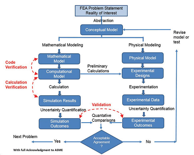 Fig. 1: ASME V&V flowchart.
The comparisons between test and analysis are based on a set of metrics (the more the better). This means that the traditional single “big target” comparison (such as ultimate failure level, maximum deflection or peak acceleration) is supplemented by many incremental metrics. These give a broader validation between model and test and also provide a richer archive of legacy data.
Early program comparisons of test and analysis can help both plans and assumptions evolve. Many companies use FEA to predict test fixture strength and stiffness. In some cases, interaction between fixture and test article is inevitable and can be quantified (dynamic interaction or fixture flexibility).
The positioning of the verification step can be seen in Fig. 1. The lower Calculation Verification step relates to the FEA QA and checking processes we should be familiar with. Interestingly, Code Verification is included upstream of that. In many cases, repeating formal benchmarks of classical solutions to check the FEA Solver accuracy would be redundant. It is assumed to be covered by reference to the FEA Vendor Verification Manual (in at least one case confusingly called the Validation Manual). We won’t discuss the Vendor Verification process in this article. However, as we move more into multiphysics, micro mechanics and other less understood areas, it may well be that Code Verification responsibility has to move away from the FEA Vendor.
Both the FEA and test paths have a step called Uncertainty Quantification. It attempts to bring some objectiveness to the maxim “Test evidence must be right, because it’s real!” Are we comparing a highly accurate test result against a poorly modeled FEA, or are both subject to an unacceptable degree of doubt?
Uncertainty Qualification
I am not qualified to comment on Uncertainty Qualification in test, but believe it is an inexact science in FEA. We have methods of assessing mesh convergence to give confidence in FEA local stresses, but they are ad hoc. A simple automated metric can mislead here, without an understanding of load paths and stress distribution. The challenge to a good understanding of why stresses occur is that it is difficult for anyone, other than an expert, to picture. This is where FEA post-processing lets us down. There is a set of tools that could be developed to allow us to understand the results in a way which is required for effective verification.
A further shortfall of current FEA practice is the assessment of uncertainty over boundary conditions and loading. Accurate modeling of these aspects can be difficult. We can carry out sensitivity studies on loading levels and line of action, boundary stiffness and others, but it is tedious to do this manually. Again, if we are serious about V&V as an industry, we need FEA tools to facilitate this.
Stages of Model Evolution
The various stages of model evolution shown in Fig. 1, can help clarify V&V planning. I will describe the FEA path, relying heavily on the definitions from the ASME and LANL.
The Conceptual Model is perhaps a misleading title, as it may not be a numerical model in any sense, but instead reflects the knowledge and information we have in our minds when assessing the structure to analyze and test (remember the integrated approach). Questions here would include what is the type of structural configuration, design objective, loading and constraint environment. Based on our experience, knowledge and training, we are going to make early decisions on modeling and test strategy. For a small-scale project this might come down to an informal plan for pre-analysis actions and data needed to be collected.
The Mathematical Model is where we commit ideas to preliminary calculations on paper, Excel, MATLAB and other programs. It may even be a simple exploratory FEA model.
How relevant is the Mathematical Model in modern FEA? Don’t we just go straight from CAD to FEA? The key here is that structural analysis is knowledge, not just data transfer. Assumptions have to be questioned and the Mathematical Model provides that catalyst. Analysis target metrics can also be set, with ballpark comparisons against test. This could be a simple, thoroughly checked load balance diagram, with supporting calculations.
Finally we get to the Computational Model, which in our case is the FEA model. It is based on the thinking behind the conceptual model and the implementation and results of the mathematical model. The full battery of V&V checks are carried out.
Validation Uncertainty
If we are validating results between test and analysis and the range of validated designs is well populated, then we are interpolating data and would hope for good predictions. However, if we have to move outside our comfort zone, as shown in Fig. 2, the process becomes more difficult. A nice quote in discussion was “rewards come with risks, and risk goes hand in hand with uncertainty.”
A judgment has to be made on whether the validation is acceptable based on:
• How complex are the physics and geometry involved;
• What degree of similarity is there between prediction point and validation domain;
• How well do test and analysis validations relate to each other;
• Is the model adequately representative.
One cautionary note: For some work the physics, problem complexity and hypothesis describing the phenomena can change, and our usual analysis method may not be appropriate. A challenging example for V&V is a commercial MEMS (micro-electro-mechanical systems) device design, electrically heating up an electrode that starts a chemical reaction in a fluid passing by, with a requirement to ensure structural, electrical and chemical integrity. Conversely, an aircraft structure analysis may not be required to demonstrate failure, but to show stresses within the elastic limit. If this level is exceeded, then a redesign is required as the limit load is established from extensive testing. This is an analysis exercise rather than a full simulation exercise.
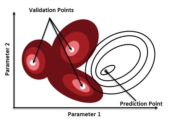 Fig. 2: Validation uncertainty as described by the LANL.
An amusing analogy is to consider whether we have to model:
• An elephant reaching a cliff edge and falling off, so we can then predict the effect of reaching within a few millimeters (simulation).
• A demonstration that barriers stop the elephant getting nearer than 50 meters to a cliff edge we think may be there (analysis).
Key Takeaways
So what is my take on the V&V process? Don’t get hung up on the words Verification and Validation in isolation, look at the process flow. Prediction and confirmation of the physics appear in Verification and Validation respectively. There is a need to make the concept of V&V more meaningful and practical at a practicing engineer/designer level. The ASME process plan is a great start. Build from existing FEA process and QA plans.
Test and analysis teams need to work together so that an integrated V&V plan can be developed; this may be a cultural challenge. Development of more generally accepted and easily applied Uncertainty Quantification in FEA is required.
Finally, the bottom line question: how does V&V help my boss, my client and me? An analyst with a V&V procedure can efficiently and effectively demonstrate his case in a consistent way. Validation against test is worth its weight in gold. The boss, who may have no FEA knowledge, has documented evidence to underwrite any go/no-go project decision. If all goes well the client should benefit from tighter and more objective decision making, if it doesn’t – Plan B should be quicker in coming!
References.
1. An Overview of the Guide for Verification and Validation in Computational Solid Mechanics. L.E. Schwer, ASME 2006
2. LA-14167-MS. Concepts of Model Verification and Validation. Ed. Charmian Schaller, LANL, 2004
Subscribe to our FREE magazine, FREE email newsletters or both!
Latest News
About the Author
Tony Abbey is a consultant analyst with his own company, FETraining. He also works as training manager for NAFEMS, responsible for developing and implementing training classes, including e-learning classes. Send e-mail about this article to [email protected].
Follow DE

