What Injection Molding Simulation Software Can Do for You
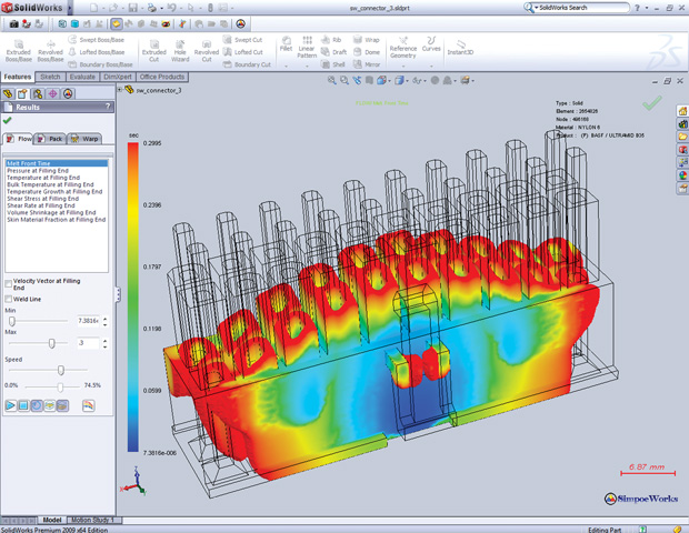
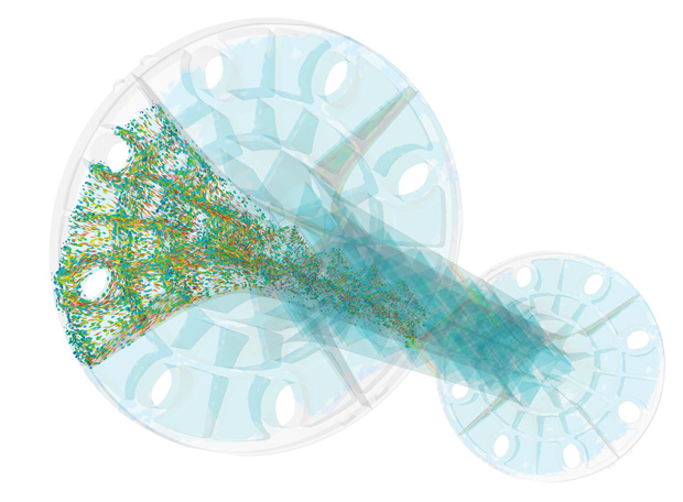
Simulation of filling an injection-molded multi-pin electronics connector, performed in SOLIDWORKS Plastics from Dassault Systèmes SOLIDWORKS. Image courtesy of Dassault Systèmes.


Latest News
February 1, 2017
It’s not just the part; it’s the process. Successful injection molding of plastic parts involves three stages: design the part to be produced; design the corresponding tool/mold; and define the process that fills the mold for manufacturing. For each of these stages, whether for part designers, mold designers or part producers, simulation software packages stand ready to identify and guide optimized approaches, with some pretty amazing results.
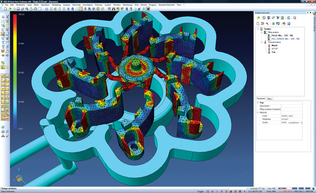 Thermal conformal-cooling analysis performed with VISI injection-molding simulation software from Vero Software. Image courtesy of Vero Software.
Thoughtful designs combine art and engineering (see “Design Considerations for Injection Molding”) generally requiring some trade-offs divided between adjusting the part design, the mold design and/or the process. Autodesk, which offers three levels of its Moldflow injection-molding simulation software, introduces the basic challenges faced by manufacturers in this field: Will the mold fill completely? Will the final part warp or have visual defects? What changes could be made to the part geometry, materials, wall thickness or gate (injection port) locations to improve the part or process? How would decreasing the cycle time or temperature affect the part quality? With these questions as starting points, experts know there’s much more work to be done.
Injection Molding Simulation Software Offerings
Fortunately, as the materials, machinery and ideas involved in injection molding have progressed, so have the capabilities of related simulation software to tackle such questions. Whether hailing from companies based in the United States the U.K., France, Germany or Japan, these packages address the concerns of everyone involved in this field, though with different ways of dividing up the tasks.
Autodesk offers two relevant packages with several levels of each: Moldflow Adviser (Premium and Ultimate) and Moldflow Insight (Standard, Premium and Ultimate), with some overlap. Hanno Van Raalte, Autodesk Moldflow product manager, notes that, for example, both Adviser Ultimate and Insight Premium cover cold and hot runner mold designs but are targeted to different users. “Adviser is intended for a designer or a manufacturing engineer who has some basic understanding of the molding process, but needs quick answers,” says Van Raalte, Typical questions would include: “Is this part design good for injection molding,” “how can I lay out a multi-cavity mold” and “how will my choices affect product quality and manufacturing cost?”
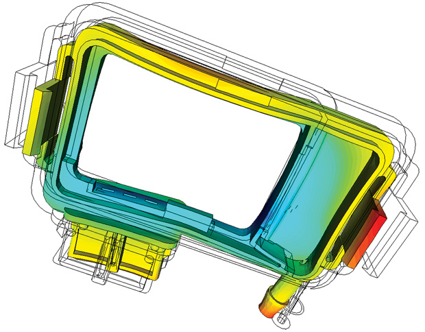
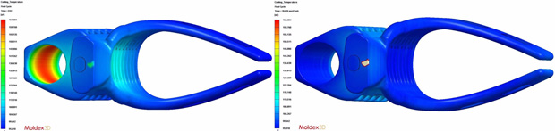 Before and after temperature distribution in a rifle stock arm-brace part manufactured by injection-molding using the original mold (left) and a redesign that incorporates conformal cooling. Linear AMS, needed reduced cooling times per cycle. By using Moldex3D simulation software, they identified areas of heat accumulation, then added conformal cooling to inner and outer regions. Cycle time dropped from 112 to 35 seconds. Images courtesy of Linear AMS.
Moldflow Adviser Premium is aimed at the part designer, while Adviser Ultimate builds on this package to also help the tooling engineer. “The Moldflow Insight product line,” explains Van Raalte, “is Adviser’s big brother and is more geared toward a specialized user, typically a plastics engineer or expert manufacturing engineer. Whereas Moldflow Adviser is tuned for speed, Moldflow Insight is tuned to provide very detailed and quantitative insight into the molding process.”
Both Moldflow product lines have access to the same plastics material database of more than 9500 materials, with each material characterized for injection molding simulation. Autodesk also has a significant mold-material database, available in Moldflow Insight, which lets users evaluate differences between, say, using an aluminum tool instead of one made from P20 tool steel. The company has recently added new capabilities that automate design changes to optimize a part for different quality objectives.
Dassault Systèmes supports injection-molding simulation for two of its major product lines. Within its SIMULIA simulation product family, the company offers Simpoe-Mold ENG for plastic part designers and Simpoe-Mold TOOL (which includes ENG) for part designers, mold designers and mold makers.
Dwayne Sawyer, growth senior solution consultant, Dassault Systèmes SIMULIA explains, for example, that while ENG lets users simulate filling and packing plus the cool-down stage for the part inside the mold, TOOL then adds support for analyzing cooling lines in the mold itself, using CFD (computational fluid dynamics) to predict where cooling is needed and FEA (finite element analysis) to calculate potential part warpage.
The company is also developing enhanced versions of these packages that will integrate in the full Dassault Systèmes 3DEXPERIENCE. The benefit will be that advanced users won’t have to go back and forth between Abaqus, CATIA and Simpoe-Mold, but instead work within a single platform. Sawyer says that hot topics for the future include the ability to run analyses of mold cores and improve simulations of both hot and cold runners.For SOLIDWORKS CAD-based users, Dassault Systemès offers an adaptation of Simpoe-Mold that uses the same simulation engine but has its own GUI (graphical user interface) and is available in three versions. SOLIDWORKS Plastics Standard is targeted to part designers, offering such information as fill time, automatic gate location and predication of sink marks. SOLIDWORKS Plastics Professional, intended for mold designers or builders, includes multi-cavity layouts, a runner design wizard, packing analysis and gas-assist injection analysis. SOLIDWORKS Plastics Premium has all these features plus advanced capabilities so CAE analysts and others can work on such tasks as designing complex cooling-line layouts, predicting part warpage and optimizing processing parameters.
A similar breakout by role and task is taken with Moldex3D simulation packages: eDesign Basic, eDesign, Moldex Professional and Moldex Advanced. “A part designer may not need to understand the detailed design of the hot runner nozzle, so he or she does not have to use the advanced hot runner module on our high level package,” says Tober Sun, division manager at Moldex3D’s Product Support Division. “But he or she has to determine if a certain boss will cause problems during filling, so Moldex3D eDesign and Professional will help them assess geometrical problems on the part design, while ignoring the more detailed mold design and processing conditions.”
All four Moldex3D products employ a full 3D boundary-layer meshing approach that offers very fast processing times; each version also supports a number of add-on modules. According to Susan Lin, support engineer at Moldex3D North America, the conformal cooling add-on is one of their best sellers. “It’s a no-brainer for users to acknowledge the benefits of conformal cooling channels,” says Lin, “if these channels are designed the right way. They have to extract heat from the exact hot area and homogenize the temperature across the part and between the mold halves. This is why simulation is needed. The benefits, including cycle time reduction and warpage improvement, can all be quantified from the simulation results.”
Other Moldex3D modules include support for design of experiments, gas- and water-assisted molding and powder-injected molding; Sun says that the next software release will add new modules such as for chemical foaming. The Moldex3D material database has more than 7000 entries (including thermosets, coolant materials and mold materials), and lets users measure and add their own material property information. For added ease of use, the Moldex3D eDesign SYNC add-on connects with SOLIDWORKS, PTC Creo and Siemens PLM Software NX, while the FEA interface supports such advanced analysis packages as SIMULIA Abaqus, ANSYS, MSC Nastran, LS-DYNA and more.
Creo Mold Analysis (CMA) is a PTC product based on Moldex3D technology. Working on top of PTC Creo, its user interface and workflow differ from that of Moldex3D, though its functionality is similar to that of Moldex3D eDesign SYNC. “The analysis object is the design model, so CMA provides injection molding process simulation for preliminary product design directly within Creo. This has reduced the need to perform exchange operations with external tools,” explains Russell Hsu, PTC Creo product management manager. He notes that two wish-list items for future CMA releases are to include design optimization and cloud computing capabilities.
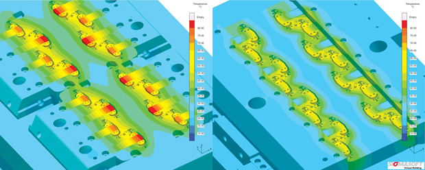 The picture shows the temperature distribution for two concepts. The left concept shows hot spots on the cavity cores whereas the right-hand layout leads to a much more homogenous temperature distribution. Image courtesy of SIGMA Engineering.
Another company that offers complementary injection molding software packages (under the VISI family name) is Vero Software. A huge advantage of the VISI modular structure is that a license can be shared across departments, supporting tasks such as part analysis, geometry validation and even a preventative flow analysis, all before a tool designer would work on the mold core/cavity and plan the manufacturing process, notes Marc Freebrey, group marketing director at Vero Software.
First, VISI Analysis offers solutions for the validation and preparation of model geometry, including splitting a model into core and cavity; creating parting and shut-off faces; checking draft angles and radii; and automatically checking for design changes. Second, based on a proprietary hybrid meshing technology, VISI Flow uses 3D flow simulation to forecast and visualize the development of the plastic melt front as well as to predict and measure the final molded shape. It addresses the complete process for part/mold designers and injection molding technicians, from filling analysis to warpage calculations to thermal optimization analyses, with options for adding to or modifying its material database.
 Simulation of filling an injection-molded multi-pin electronics connector, performed in SOLIDWORKS Plastics from Dassault Systèmes SOLIDWORKS. Image courtesy of Dassault Systèmes.
The third related product, VISI Mold, is targeted to the tool designer and allows users to work with either solid, surface, wireframe or a combination of all three formats for maximum flexibility. Users can access a design wizard to simplify creating cooling channels, import intelligent standard components whose dimensions automatically adjust to fit mold parameters, and readily create undercut release mechanisms such as side actions and lifters.
A la Carte or All-Inclusive?
Other simulation companies structure their injection molding software products in different ways. Simcon markets three fundamental packages in its Cadmould 3D-F line: ESSENTIAL, RAPID and FILL, all based on the same high-end solver—along with 25 add-on or stand-alone modules that target different materials, processes, analysis types and more.
Cadmould ESSENTIAL is termed the starter software: It simulates the filling process so that users can optimize the position and number of gates, detect weld lines and air traps, and determine cooling time and part volume. Cadmould RAPID performs these tasks along with automatic gate placement, and also generates custom reports. Cadmould FILL builds on RAPID and brings it to expert-level with the addition of tasks such as visualizing hot and cold runner systems, balancing the gating system for multiple-gate parts and using DOE (design of experiments) for optimizing process parameters.
Add-on modules to Simcon’s Cadmould FILL bring advanced capabilities. For example, Cadmould WARP simulates part shrinkage and warping at demolding and after cool down to room temperature, and accounts for parameters such as pressure distribution during packing. Cadmould COOL calculates conventional, conformal and impulse cooling functions, and handles different cooling agents and different materials for molds and inserts. The Cadmould add-ons FIBER, FOAM, RUBBER and THERMOSETS help users work with those specific materials, while bundled software is also available (e.g., Warp Expert includes FILL, PACK, FIBER and WARP).
 Shrinkage and warpage of an injection-molded part (after cool-down to ambient temperature), as simulated with Simcon’s Cadmould 3D-F line of injection-molding software products. Image courtesy of Simcon.
The company is very focused on automatic optimization of part, mold and process and thus has developed additional products with this in mind, according to Bernhard Helbich, Simcon managing director. A package called Varimos combines injection molding simulation with design of experiments and optimization, which the company says can cut down mold iterations by up to 50% and development time by up to 30%. And, through its partnership with PART Engineering, Simcon markets CONVERSE, an advanced mechanical analysis package that couples process and structure interactions (like weld lines and fiber orientations) for predicting part stiffness or failure.
Taking a somewhat different approach, SIGMA Engineering builds its SIGMASOFT products around a single Virtual Molding principle based on finite volumes that creates a 3D simulation of flow, heat flux and warpage. This allows part designers, tool makers and part manufacturers to reproduce processing conditions over multiple consecutive production cycles, which the company says is critical to understanding the complex heat-transfer conditions required to reach equilibrium. SIGMA Engineering structures its simulation products to fit the requirements of particular end-materials or processes, offering SIGMASOFT Thermoplast, SIGMASOFT Thermoset, SIGMASOFT Elastomer and even SIGMASOFT MIM/CIM (for metal and ceramic powders).
The main differences between offerings are the material types for each full-function package (individually licensed), says Vanessa Schwittay, marketing manager, Engineering at SIGMA Engineering. “Different models for the material data are used,” explains Schwittay, “and of course you have some specific results, e.g., crystallization for SIGMASOFT Thermoplast or powder-binder separation in SIGMASOFT MIM/CIM. Also depending on the material, different material and flow models may be used.” She notes that some of the next big features for their software will be DOE and autonomous optimization functionalities.
The phrase “last but not least” comes to mind when describing Transvalor’s REM3D injection molding process simulation package. Launched in 2014, it builds on the more than 30-year Transvalor legacy of simulation software for forming processes. REM3D helps users not only simulate filling, determine packing time and identify best gate positions, but also adds many advanced features, such as handling water- and gas-assisted injection molding, overmolding, fiber reinforced materials, polyurethane foams, thermoset materials, injection-compression and injection of highly viscous fluids.
 Fiber orientation simulation of an injection-molded filled-plastic foot-section for a piece of furniture, performed with REM3D software from Transvalor. Image courtesy of Solvay.
Noting the range of advanced capabilities in REM3D, Nicolas Poulain, Transvalor technical manager, says: “Users do not need to have any knowledge of Navier-Stokes equations or any FEM background. The input data are process-related such as cavity design, material grade and initial melt temperature. Thanks to our revolutionary Automatic, Anisotropic and Adaptive (AAA) re-meshing technique, the user does not even have to worry about the mesh definition; the solver will refine the mesh as-needed, automatically.”
REM3D offers a user-adaptable material database that includes characterizations for foam material properties. Transvalor is also working to incorporate the standard database known as CAMPUS (Computer-Aided Material Preselection by Uniform Standards), which will add an additional 10,000 entries to REM3D resources.
More Info
Subscribe to our FREE magazine, FREE email newsletters or both!
Latest News
About the Author
Pamela Waterman worked as Digital Engineering’s contributing editor for two decades. Contact her via .(JavaScript must be enabled to view this email address).
Follow DE

